
Youchao Jiang, Guobin Ren, Yudong Lian, Yu Liu, Huaiqing Liu, Haisu Li, Wenhua Ren, Wei Jian, Shuisheng Jian, "Multilayer-core fiber with a large mode area and a low bending loss," Chin. Opt. Lett. 14, 120601 (2016)
- Chinese Optics Letters
- Vol. 14, Issue 12, 120601 (2016)
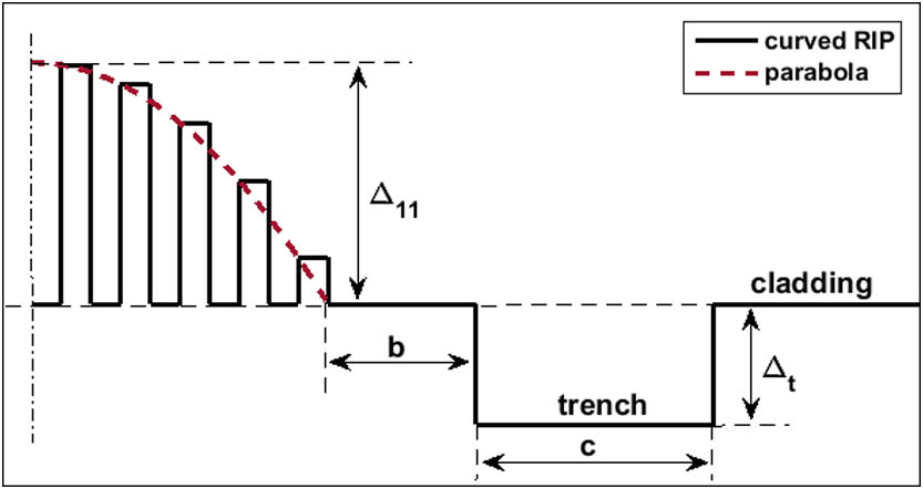
Fig. 1. RIP of an MAF with a curved RIP and a trench in the cladding.
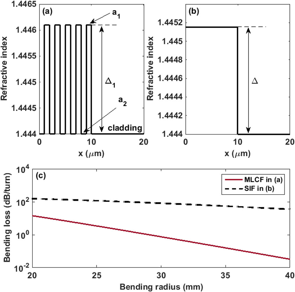
Fig. 2. (a) Uniform high-index layer MLCF with parameters Δ 1 = 0.0021 a 1 = 1 μm a 2 = 1 μm Δ = 0.00115
Fig. 3. (a) Uniform high-index layer MLCF with parameters Δ 1 = 0.0021 a 1 = 1 μm a 2 = 1 μm 6 ) with Δ 11 = 0.004
Fig. 4. Bending loss evolution as a function of core-trench separation b
Fig. 5. (a) b A b A r b A
Fig. 6. Bending loss comparison between the MLCF with a trench and the MLCF without a trench.
Fig. 7. RIP of the fabricated fibers. The inset is the micrograph of the MLCF.
Fig. 8. Measured dispersion of the fabricated MLCF and SMF-28.
Fig. 9. Spectral bending loss as a function of the bending radius and wavelength.
Fig. 10. Comparison of the bending losses between the fabricated MLCF and the SMF-28 fiber at 1310 and 1550 nm. The curves and markers represent the results of the simulation and the measurement, respectively.
Fig. 11. (a) Comparison of the measured and calculated bending loss as a function of the wavelength, with a bending radius of 5 and 10 mm.
|
Table 1. Attributes of MLCF and SMF–28 Fiber


Set citation alerts for the article
Please enter your email address

© Copyright 2018-2021 | Chinese Laser Press. All Rights Reserved 沪ICP备15018463号-20