
Wei Hou, Jing Chen, Songlin Chu, Xiuzhuan Wang, Zhiyi Yang, Yuqi Zhang, Weibin Teng. Anisotropy of Microstructure and Tensile Properties of AlSi10Mg Formed by Selective Laser Melting[J]. Chinese Journal of Lasers, 2018, 45(7): 0702003
- Chinese Journal of Lasers
- Vol. 45, Issue 7, 0702003 (2018)
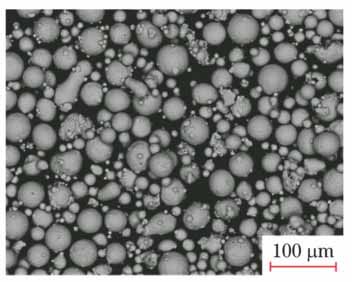
Fig. 1. SEM image of AlSi10Mg powder
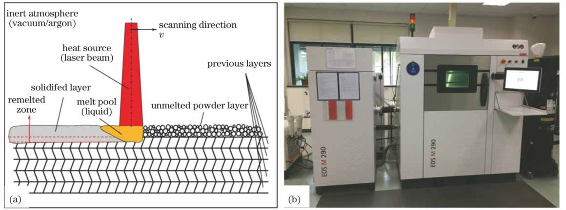
Fig. 2. (a) Schematic drawing of SLM technology based on powder bed; (b) SLM equipment of EOS M290
Fig. 3. (a) AlSi10Mg cubic sample formed by SLM; (b) size of tensile sample; (c) AlSi10Mg tensile samples formed by SLM
Fig. 4. (a) Three-dimensional microstructure image of AlSi10Mg cubical sample formed by SLM, the red dashed lines show the scanning strategy; (b)-(c) enlarged morphology of A, B, C surfaces, the red dashed lines show the boundary of melt pool
Fig. 5. Phase diagram of aluminum-silicon (the red dashed line shows the solidification path and phase transformation of Al-10Si)[20]
Fig. 6. Schematic drawing of solid-liquid interface of SLM formed AlSi10Mg alloy melt pool
Fig. 7. Cellular and dendrite zones in SLM formed AlSi10Mg melt pool
Fig. 8. SEM morphology of A plane of cubical AlSi10Mg sample formed by SLM (the white dashed line shows the boundary of melt pool and the white arrows present the growth direction of dendrites)
Fig. 9. SEM morphology of C plane of cubical AlSi10Mg sample formed by SLM
Fig. 10. Schematic of morphological evolution of Al-Si eutectic structure in different zones of melt pool in SLM formed AlSi10Mg
Fig. 11. Room temperature tensile properties of SLM formed AlSi10Mg alloy in transverse and longitudinal directions. (a) Strength; (b) elongation
Fig. 12. SEM tensile fractures of SLM formed AlSi10Mg alloy at room temperature. (a)-(c) Longitudinal sample; (d)-(f) transverse sample
Fig. 13. Crack formation of SLM formed AlSi10Mg alloy in tensile process at room temperature
|
Table 1. Chemical composition of AlSi10Mg powder%
|
Table 2. Processing parameters used in SLM
|
Table 3. Tensile results of SLM formed AlSi10Mg alloy sample in longitudinal and transverse directions and die-casting alloy sample

Set citation alerts for the article
Please enter your email address
© Copyright 2018-2021 | Chinese Laser Press. All Rights Reserved 沪ICP备15018463号-20