
Shuangxiang Zhao, Qingwen Liu, Yuanyuan Liu, Huilian Ma, Zuyuan He, "Navigation-grade resonant fiber-optic gyroscope using ultra-simple white-light multibeam interferometry," Photonics Res. 10, 542 (2022)
- Photonics Research
- Vol. 10, Issue 2, 542 (2022)
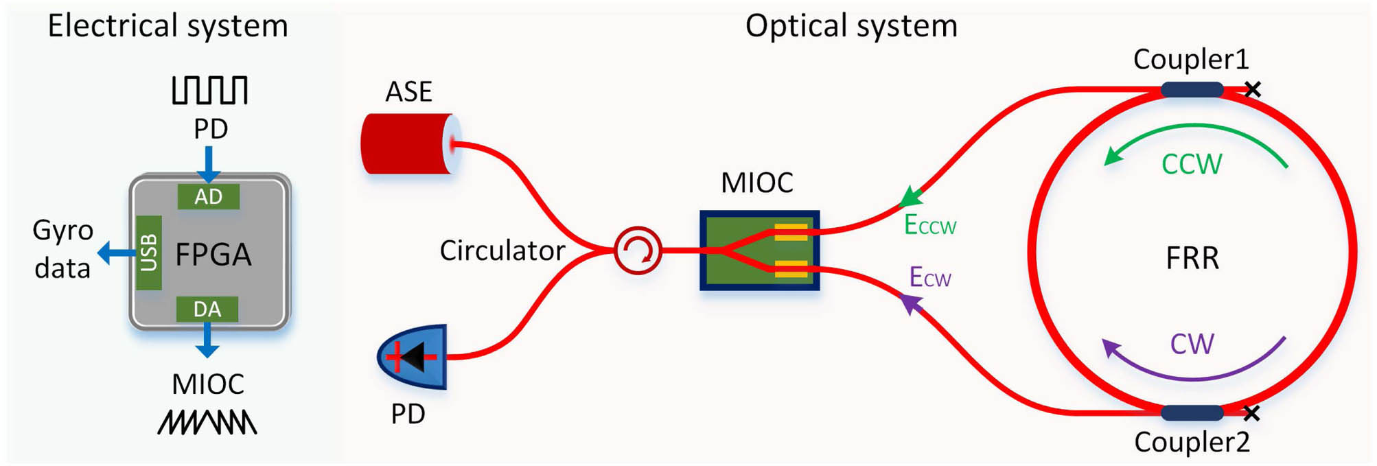
Fig. 1. RFOG setup. ASE, amplified spontaneous emission; PD, photodetector; FPGA, field programmable gate array; MIOC, multifunction integrated-optics chip; FRR, fiber ring resonator; CW, clockwise; CCW, counterclockwise; AD, analog-to-digital; DA, digital-to-analog. Different from traditional IFOGs based on the minimal scheme, the long fiber coil is replaced with a high-finesse FRR. A photograph of the RFOG setup is also provided in Fig. 8 in Appendix A .
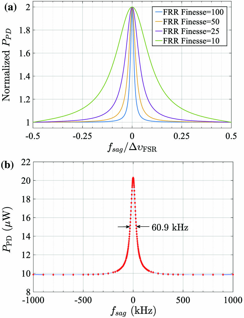
Fig. 2. (a) Simulation analysis and (b) experimental demonstration of Eq. (4 ). They are the outputs of the proposed white-light multibeam interferometry and are defined as the response curves of the proposed RFOG.
Fig. 3. Modulation signals and the corresponding P PD V MIOC V π f mod
Fig. 4. (a) Demodulation process in the FPGA; (b) measured error signal versus f sag
Fig. 5. Test results of the RFOG. Gyro readout under sinusoidal rotation of (a) 10°/h, (b) 1°/h, and (c) 0°/h; (d) moving average of the static test data in (c) with a time window of 1000 s; (e) spectral power density of the results in (a)–(c); (f) Allan deviation of the static test data in (c).
Fig. 6. RIN of P PD P in
Fig. 7. Scheme of introducing equivalent Sagnac frequency via sawtooth modulation. (a) Modulation waveforms at two arms of the MIOC; (b) modulation process and scheme.
Fig. 8. Photograph of the RFOG system. PC, personal computer.
|
Table 1. Parameters of the RFOG
|
Table 2. Comparison between the Proposed RFOG and Traditional FOGs


Set citation alerts for the article
Please enter your email address

© Copyright 2018-2021 | Chinese Laser Press. All Rights Reserved 沪ICP备15018463号-20