Author Affiliations
1School of Optical and Electronic Information, National Engineering Research Center for Next Generation Internet Access-System, Wuhan National Laboratory for Optoelectronics, Huazhong University of Science and Technology, Wuhan 430074, Hubei , China2School of Future Technology, Huazhong University of Science and Technology, Wuhan 430074, Hubei , Chinashow less
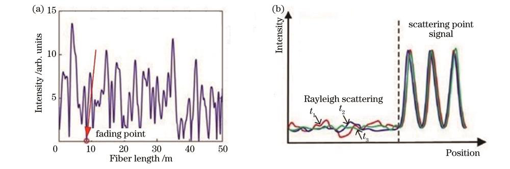
Fig. 1. Backscattering signal. (a) Coherent fading phenomenon; (b) comparison of scattering enhancement signal and Rayleigh scattering signal
Fig. 2. Fabrication process of scattering enhanced microstructure fiber. (a) Drawing of online grating technology preparation system for wire drawing tower
[14]; (b) OTDR trace map of UWFBG array
[14]; (c) comparison of signals of scattering enhanced fiber and ordinary single mode fiber
[16] Fig. 3. UV-transparent fiber on-line fabrication and its results. (a) Online grating technology based on UV coated optical fibers
[18]; (b) discrete scattering enhanced fiber
[12]; (c) continuous scattering enhanced fiber
[19]; (d) hybrid encoding grating array spectra
[20]; (e) gradient scattering enhanced fiber spectra
[21] Fig. 4. Colorless weak reflection point fabrication and its result. (a) Colorless weak reflection point preparation system diagram; (b) comparison of fiber backscattered light signals before and after preparation
Fig. 5. Typical DAS performance improvement scheme based on scattering enhanced fiber. (a) Low frequency drift compensation scheme
[29]; (b) frequency response band expansion scheme
[33]; (c) detection distance expansion scheme
[21]; (d) spatial resolution improving scheme
[30] Fig. 6. Secondary coated WFBG array fiber optic cable
[41]. (a) Schematic diagram of WFBG array fiber; (b) time domain reflected light intensity of WFBG array fiber; (c) physical image of WFBG array fiber
Fig. 7. Backscatter enhanced fiber quasi distributed sensitization array
[12]. (a) Schematic diagram of backscatter enhanced fiber; (b) backscatter intensity of backscatter enhanced fiber; (c) array diagram
Fig. 8. Fully distributed sensitization optical cable
[46]. (a) Schematic diagram; (b) physical image
Fig. 9. Basic structure and sensing principle of OFDR
Fig. 10. High density scattering enhanced fiber. (a) Ge doped photonic crystal fiber
[63]; (b) continuously exposed single mode fiber
[64]; (c) UV exposed transparent UV coated fiber
[19] Fig. 11. Shape sensing fiber. (a) Parallel multi-core fiber with engraved Bragg grating
[68];(b) scattering enhanced fiber parallel fiber cluster
[69]; (c) spiral multi-core fiber with engraved Bragg grating
[72]; (d) spiral fiber cluster of scattering enhanced fiber
[73] | Performance | Scheme | Institution | Ref. No |
|---|
| Compensation of low-frequency phase drift | Auxiliary interferometer | Shanghai Jiao Tong University | [28] | | Reference fiber compensation+temperature hysteresis compensation | Huazhong University of Science and Technology | [29] | | Spatial resolution improvement | Pulse linear sweeping | Shanghai Jiao Tong University | [30] | | Pulse coding | University of Electronic Science and Technology of China | [31] | | Frequency response expansion | Frequency multiplexing | Nanjing University | [32] | | Time-slot multiplexing | Huazhong University of Science and Technology | [33] | | Detection distance increase | End scattering enhancement | University of Southampton | [34] | | Gradient scattering enhancement | Huazhong University of Science and Technology | [21] |
|
Table 1. Exploration of improving DAS performance based on scattering enhanced fiber
| Sensitization enhanced technology | Sensitivity | Diameter | Maximum cable length | Frequency response flatness | Fully distributed detection |
|---|
| Secondary coating sensitization | Moderate | Ultra-thin | Maximum sensing distance of the system | Relatively poor | Yes | | Quasi-distributed sensitization | High | Moderate | Related to the length of the elementary winding coil and the elementary spacing | Good | Yes | | Fully distributed sensitization | High | Moderate | Maximum sensing distance/winding ratio | Good | Yes |
|
Table 2. Comparison of three sensitization enhanced technologies for scattering enhanced fiber
| Field | Monitoring parameter | Year | Overview of research | Ref. No |
|---|
| Pipeline monitoring | Corrosion defect | 2020 | Defect identification accuracy exceeds 94% | [47] | | Pipeline flow rate | 2020 | High precision detection of pipeline flow through scattering enhanced optical fibers | [48] | | External invasion | 2022 | Recognition accuracy of external rupture events in complex environments is greater than 85% | [49] | | Leakage identification | 2023 | Leakage with a small scale of 0.5 mm can be monitored through scattering enhanced optical fibers | [50] | | Target detection | Unmanned aerial vehicle | 2023 | Enhanced fiber optic acoustic sensors(FOASs)are used to detect UAV,with a measurement sensitivity of -101.21 re:1 rad/µPa | [44] | | Marine seismic survey | 2022 | Fully continuous fiber optic sensitized streamer with sensitivity of -137 dB re:1 rad/(μPa·m) | [51] | | Underwater target | 2023 | Distributed sensitizing cable sound pressure sensitivity of -137.2 dB re:1 rad/(μPa·m) | [46] | | Structural health monitoring | Track defects | 2022 | Multiple defects can be successfully identify and locate along the railway line,with a standard deviation of 0.314 m | [52] | | Tunnel safety | 2021 | Tunnel reinforcement steel ring structure monitoring,recognition rate is larger than 97.8% | [53] | | Building intrusion | 2022 | Scattering enhanced optical fiber is used for intrusion detection around facilities,with a detect distances of >100 feet | [54] | | Extreme environment | 2021 | Femtosecond laser engraved optical fiber,extreme temperature sensing(1000 ℃) | [55] | | Geological resource exploration | Oil exploration | 2021 | Recording direct and reflected seismic waves in a vertical well with microstructure optical fibers | [56] | | VSP | 2019 | Clear and high signal-to-noise ratio VSP waveform is obtained | [57] | | Fault exploration | 2020 | Deep imaging of stratigraphic data can detect the intersection fault of two underground boreholes | [58] | | Oil well temperature measurement | 2020 | High-temperature resistant scattering enhanced optical fiber is developed,with extra 1 year lifespan at 150 ℃ | [59] | | Subsea oil field | 2020 | Enhanced Rayleigh scattering cable to obtain multi well data for image coverage | [60] |
|
Table 3. Typical application progress of distributed acoustic sensing technology
| Application scenario | Specific application | Institution | Ref. No |
|---|
| Structural health monitoring | Distributed strain detection of commercial aircraft wings | LUNA company | [74] | | Distributed monitoring helicopter blade deflection | Japan Aerospace Exploration Agency | [75] | | High-density distributed crack tip sensing and monitoring | Wuhan University of Technology | [76] | | Strain field monitoring system in ship transverse under hydrostatic | Wuhan University of Technology | [77] | | Shape sensing | Shape sensing-assisted epi-dural needle guidance | Nazarbayev University | [78] | | Medical catheter position tracking | Intuitive company | [79] | | Shape reconstruction of medical catheters | University of Leuven | [80] |
|
Table 4. Typical applications of distributed strain/deformation sensing technology

![Fabrication process of scattering enhanced microstructure fiber. (a) Drawing of online grating technology preparation system for wire drawing tower[14]; (b) OTDR trace map of UWFBG array[14]; (c) comparison of signals of scattering enhanced fiber and ordinary single mode fiber[16]](/richHtml/gxxb/2024/44/1/0106008/img_02.jpg)
