
Fan Zhang, Beibei Qi, Baijin Su, Ou Xu, Yuwen Qin, "High sensitivity all-fiber bend sensor based on modal interferences in a ring core fiber," Chin. Opt. Lett. 21, 051201 (2023)
- Chinese Optics Letters
- Vol. 21, Issue 5, 051201 (2023)
Abstract
1. Introduction
Optical fiber sensors (OFSs) have been widely investigated in various measurements, for instance, temperature[1], humidity[2], refractive index[3], strain[4], curvature[5], liquid level[6], and torsion[7,8]. Bending measurement plays a significant role in robotics applications, structural health monitoring, etc. Different types of optical fiber bend sensors have been reported, based on devices such as fiber Bragg gratings (FBGs), long-period fiber gratings (LPFGs), Mach–Zehnder interferometers (MZIs), Fabry–Perot interferometers (FPIs), Michelson interferometers (MIs), and multimode interferometers (MMIs).
The development of optical fiber sensors closely depends on optical fiber manufacturing technology. In recent years, the unique ring core fiber (RCF) with ring refractive index layer, is designed for mode-division multiplexing (MDM) and orbital angular momentum (OAM) transmission[9]. In 2019, Xuan et al. reported a microfiber MZI based on RCF and measured the temperature and refractive index[10]. The experimental results show that the temperature and refractive index sensitivities are around 64 pm/°C and 44 nm/RIU, respectively. Similarly, Yu et al. proposed a high-sensitivity microfiber MZI temperature sensor[11]. The sensor was fabricated by heating and stretching an RCF with the hydrogen flame. The sensitivity is 186.6 pm/°C when the cladding diameter of RCF is 72.58 µm. In 2021, Wei et al. proposed a sensor for simultaneous measurement of temperature and curvature by the RCF[12]. At the same time, they reported an RCF MZI with dual demodulation of temperature and refractive index[13]. In 2022, Dong et al. reported an optical curvature sensor with a high resolution based on an in-line fiber MZI and microwave photonic filter[14]. Bai et al. proposed a curvature sensor, which is fabricated by splicing a segment of RCF between two pieces of single-mode fibers (SMFs) with two up-tapers[15]. Our previous works proposed an MZI curvature sensor based on the SMF–RCF–SMF structure[5]. The sensor was fabricated by splicing a segment of RCF between two pieces of SMF. The curvature measurement can be achieved by monitoring wavelength shifts of the interference dip. The experimental results show that the curvature sensitivity is
The above reported sensors are mainly based on wavelength interrogation. In addition to wavelength interrogation, intensity interrogation can be used to achieve sensing measurements. Dong et al. proposed an intensity-modulated fiber sensor for bending measurement[16]. Zhang et al. fabricated a bending sensor based on fiber-optic spindle arrays[17]. Bend sensing for intensity interrogation was achieved using an SMF spiral structure by He et al.[18]. Marrujo-Garcia et al. reported a temperature-independent curvature sensor based on in-fiber MZI using hollow-core fiber[19]. The curvature sensitivity of the proposed sensor reached
Sign up for Chinese Optics Letters TOC. Get the latest issue of Chinese Optics Letters delivered right to you!Sign up now
This paper proposed and experimentally demonstrated a high sensitivity bend sensor using modal interferences and intensity interrogation. The sensor was fabricated by splicing a segment of RCF between two pieces of multimode fibers (MMFs), forming an MMF–RCF–MMF (MRM) structure. Then the structure of MRM is sandwiched between the lead-in and lead-out SMFs. Due to the mode mismatch, multiple modes are excited in the RCF. Results show that the average bend sensitivity for intensity is
2. Sensor Principle
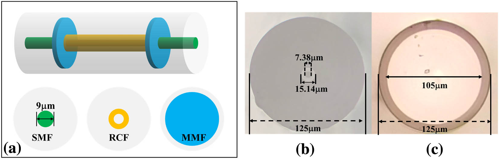
The schematic diagram of the proposed sensor is illustrated in Fig. 1(a). First, the lead-in SMF is spliced with the MMF by the automatic splicing mode of the fusion splicer (Atomo WAVE SFS-A63), and then the MMF is cut to the selected length. Second, the lead-out SMF and MMF are spliced and cut in the same way. Finally, a 10 mm long RCF is fused between the two MMF sections in a cladding-aligned manner. The RCF is composed of a ring core, a silica center, and outer cladding, the cross-sectional microscopic view of which is shown in Fig. 1(b).
![]()
Figure 1.(a) Schematic of the proposed sensor. Cross-sectional microscope view of (b) RCF and (c) MMF.
The ring core, silica center, and cladding diameters are 15.14, 7.38, and 125 µm, respectively. The core and cladding refractive indices of RCF are 1.4728 and 1.4597, separately. The core and cladding diameters of the MMFs are 105 and 125 µm, respectively, a cross-sectional microscopic view of which is shown in Fig. 1(c). The core diameter, cladding diameter, and mode field diameter (MFD) of the SMF are 9, 125, and 10.2 µm, respectively.
In the proposed scheme, the MMFs play the role of a coupler for splitting and coupling. At the same time, to avoid phase differences between different modes in the MMF, the lengths of the MMF are limited to no more than 1 mm[20]. Considering the possibility of fusion and the compactness of the structure, the length of the RCF is set to 10 mm. To understand the effect of the MMF in the structure, the propagation field distribution is simulated by the beam propagation method. Figure 2(a) displays the light transmission in the SMF–RCF–SMF (SRS) structure. It can be seen that the energy is mainly distributed in the ring core and silica center, and the cladding only has weak leakage energy. In Figs. 2(b) and 2(c), simulation results of the SMF–MMF–RCF–SMF (SMRS) and SMF–MMF–RCF–MMF–SMF (SMRMS) structures are shown, respectively. Compared with the SRS, the energy in the RCF cladding is significantly enhanced for the SMRS and SMRMS structures. And the SMRMS recouples light from the RCF to the lead-out SMF with high efficiency due to the second segment of the MMF. The incident light from the SMF will first be coupled and expanded in the MMF1. Then this expanded beam is split and enters the RCF, exciting multiple modes in the RCF. Since these modes have different refractive index values, the optical path differences will be produced between any two of them. As a result, when these modes are recoupled into MMF2, modal interferences are formed.
![]()
Figure 2.Propagation field distribution with different structures. (a) SMF–RCF–SMF; (b) SMF–MMF–RCF–SMF; and (c) SMF–MMF–RCF–MMF–SMF.
The interference spectrum dips will locate at
Fiber bending causes strain change and disturbs the refractive index distribution of the cross section, which will lead to the deformation of mode fields. In Fig. 3, the refractive index distributions of the straight (blue curve) and bent (red curve) fibers are plotted, and it is evident that the bending causes a redistribution of the refractive index in the fiber. It means the effective refractive index of the ring core mode, silica center mode, and cladding mode will be changed. The mode field changes also induce energy redistribution among the ring core, silica center, and cladding areas, leading to alterations of interference fringes. The inset of Fig. 3 shows the simulation results of the light field distribution of the straight and bending fibers at
![]()
Figure 3.Schematic diagram of the refractive index distribution of straight and bending fibers. The inset shows simulation results of the light field distribution at Z = 6500 µm.
The transmission spectrum of the proposed sensor based on the SMRMS structure is displayed in Fig. 4(a). The FSR and extinction ratio (ER) are 15.8 nm and 8.8 dB. Figure 4(b) shows the spatial frequency spectrum of the transmission by fast Fourier transform (FFT). The multiple peaks in the spatial frequency spectrum verify that multiple modes are excited and participate in the interference. The dominant peak at zero corresponds to the fundamental mode. The frequencies of the three main peaks except the fundamental mode are
![]()
Figure 4.(a) Measured transmission spectrum; (b) FFT of measured spectrum.
By transforming Eq. (3), the refractive index difference can be written as
First, the refractive index of the RCF fundamental mode was calculated using the finite element method (FEM) to be 1.4685. Then, according to Eq. (4), the effective refractive index differences between the three main peaks and the fundamental mode are calculated as 0.0021, 0.0036, and 0.0126. They correspond to the core mode (
![]()
Figure 5.Mode field distribution are obtained by using FEM. (a) LP21; (b) LP31; (c) LP29.
3. Experiment and Discussion
Figure 6 is a schematic diagram of the bend sensing system. A broadband source (BBS) with a range from 1250 to 1650 nm is the light source. An optical spectrum analyzer (OSA, Yokogawa, AQ6370D) is used to monitor changes in the transmission spectrum of the sensor. The sensor is fixed on a pair of 3D translation stages with an initial distance of
![]()
Figure 6.Experimental setup for the curvature measurement.
The resonance dip around 1450 nm is chosen to indicate the bending-induced change in the transmission spectrum, as shown in Fig. 7(a). It can be found that the dip wavelength shifts to a longer wavelength with the curvature increase, and the intensity decreases with the curvature increase. The relationship between the average wavelength drift and bending for the four measurements are shown in Fig. 7(b). The inset shows the linear fitting of four testing results. The maximum wavelength curvature sensitivity is
![]()
Figure 7.(a) Interference dip (at 1450 nm) evolution with different curvatures; (b) average wavelength-bending response with error bars for four testing results; the inset shows linear fitting of the four measurements.
![]()
Figure 8.Average intensity-bending response with error bars for four testing results; the inset shows the linear fitting of the four measurements.
The results of the four measurements according to Figs. 7(b) and 8 show that the sensor has good repeatability. For wavelength shift, the maximum standard deviation of the four measurements is 0.05 nm, which corresponds to a bending error of
Finally, the temperature responses of the sensor are also measured, and the results are displayed in Fig. 9, with temperature increasing from 30°C to 70°C. Based on Fig. 9(a), it can be found that the dip wavelength shifts to a longer wavelength as the temperature increases. The wavelength sensitivity of temperature is 64 pm/°C with an R-square value of 0.97. The maximum temperature sensitivity is 0.096 dB/°C at a temperature of 30°C. The intensity varies nonlinearly with temperature, with an average sensitivity of 0.045 dB/°C.
![]()
Figure 9.(a) Spectral responses under different temperatures; (b) wavelength and intensity response to temperature.
The experimental results show that the average bend sensitivity for intensity interrogating are
For comparison with the results in the existing literature, some of the reported bending sensors are listed in Table 1. In Ref. [18], these helicoidal long-period fiber gratings are fabricated by twisting SMFs during
| Structure | Sensitivity ( | Complexity of Manufacturing Process | Ref. |
|---|---|---|---|
| Helicoidal LPFGs | 4.1 | Complex | [ |
| Superimposed grating | 0.6 | Complex | [ |
| Fiber spindle arrays | −38.4 | Moderate | [ |
| NCF–SCF–NCF | 10.22 | Simple | [ |
| SMF helical | −7.524 | Complex | [ |
| Taper–DCF | 2.88 | Simple | [ |
| MMF–RCF–MMF | −25.63 | Simple | This work |
Table 1. Performance Comparison between Our Sensors and Other Sensors
4. Conclusions
In conclusion, a simple and cost-effective bend sensor based on the RCF has been proposed by simply splicing a short segment of RCF with two segments of MMFs. By monitoring the wavelength and intensity changes of the characteristic interference dip (at 1450 nm), the sensor can realize the measurement of bending and temperature. The sensor has a high sensitivity of
References


Set citation alerts for the article
Please enter your email address

© Copyright 2018-2021 | Chinese Laser Press. All Rights Reserved 沪ICP备15018463号-20