
Yichen Song, Yufeng Tang, Tao Lai, Peiqi Yuan, Xiaowei Ding, Shan Mao, Jianlin Zhao. Design of a Solar Blind Ultraviolet Refractive-Diffractive Hybrid Zoom Optical System[J]. Acta Optica Sinica, 2024, 44(4): 0422003
- Acta Optica Sinica
- Vol. 44, Issue 4, 0422003 (2024)
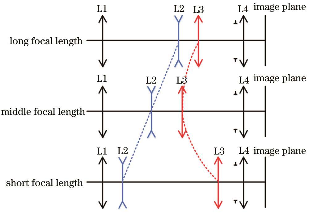
Fig. 1. Principle of mechanical zoom optical system

Fig. 2. Two-dimensional diagrams of optical system under different focal lengths. (a) f '=40 mm; (b) f '=70 mm; (c) f '=100 mm
Fig. 3. MTF of optical system under different focal lengths. (a) f '=40 mm; (b) f '=70 mm; (c) f '=100 mm
Fig. 4. Seidel diagrams of optical system under different focal lengths. (a) f '=40 mm; (b) f '=70 mm; (c) f '=100 mm
Fig. 5. Two-dimensional diagrams of ultraviolet optical system under different focal lengths. (a) f '=40 mm; (b) f '=70 mm; (c) f '=100 mm
Fig. 6. Cross section curves of even aspherical surface and standard surface
Fig. 7. Diffraction efficiency and phase distribution of designed diffractive optical element. (a) Diffraction efficiency; (b) phase
Fig. 8. Diagrams of Qcon aspherical and standard surfaces. (a) Two-dimensional diagram; (b) three-dimensional Qcon aspherical surface
Fig. 9. MTF of ultraviolet optical system under different focal lengths. (a) f '=40 mm; (b) f '=70 mm; (c) f '=100 mm
Fig. 10. Field curvature and distortion of ultraviolet optical system under different focal lengths. (a) (d) f '=40 mm; (b) (e) f '=70 mm; (c) (f) f '=100 mm
Fig. 11. Cam curves of the zoom lens
Fig. 12. Image simulation results of ultraviolet optical system under different focal lengths. (a) Fingerprint image; (b) f '=40 mm; (c) f '=70 mm; (d) f '=100 mm
|
Table 1. Design index of ultraviolet optical system
|
Table 2. Structure parameters of optical system
|
Table 3. Parameters of aspherical surface
|
Table 4. Parameters of diffractive surface
|
Table 5. Parameters of Qcon asphere
|
Table 6. Tolerance data of system
|
Table 7. Tolerance analysis results

Set citation alerts for the article
Please enter your email address
© Copyright 2018-2021 | Chinese Laser Press. All Rights Reserved 沪ICP备15018463号-20