• Photonics Research
  • Vol. 6, Issue 5, B30 (2018)
Xingyuan Xu1、†, Jiayang Wu1、†, Thach G. Nguyen2, Tania Moein1, Sai T. Chu3, Brent E. Little4, Roberto Morandotti5、6、7, Arnan Mitchell2, and David J. Moss1、*
Author Affiliations
  • 1Centre for Micro-Photonics, Swinburne University of Technology, Hawthorn, VIC 3122, Australia
  • 2ARC Centre of Excellence for Ultrahigh-bandwidth Devices for Optical Systems (CUDOS), RMIT University, Melbourne, VIC 3001, Australia
  • 3Department of Physics and Material Science, City University of Hong Kong, Tat Chee Avenue, Hong Kong, China
  • 4State Key Laboratory of Transient Optics and Photonics, Xi’an Institute of Optics and Precision Mechanics, Chinese Academy of Sciences, Xi’an 710119, China
  • 5INRS-Énergie, Matériaux et Télécommunications, 1650 Boulevard Lionel-Boulet, Varennes, Québec J3X 1S2, Canada
  • 6National Research University of Information Technologies, Mechanics and Optics, St. Petersburg, Russia
  • 7Institute of Fundamental and Frontier Sciences, University of Electronic Science and Technology of China, Chengdu 610054, China
  • show less
    DOI: 10.1364/PRJ.6.000B30 Cite this Article Set citation alerts
    Xingyuan Xu, Jiayang Wu, Thach G. Nguyen, Tania Moein, Sai T. Chu, Brent E. Little, Roberto Morandotti, Arnan Mitchell, David J. Moss. Photonic microwave true time delays for phased array antennas using a 49  GHz FSR integrated optical micro-comb source [Invited][J]. Photonics Research, 2018, 6(5): B30 Copy Citation Text show less
    Scheme of the proposed TTDL based on an integrated optical comb source. TLS, tunable laser source; EDFA, erbium-doped fiber amplifier; BPF, optical bandpass filter; PC, polarization controller; TCS, temperature controller stage; MZM, Mach–Zehnder modulator; SMF, single-mode fiber; WDM, wavelength division multiplexer; PD, photodetector.
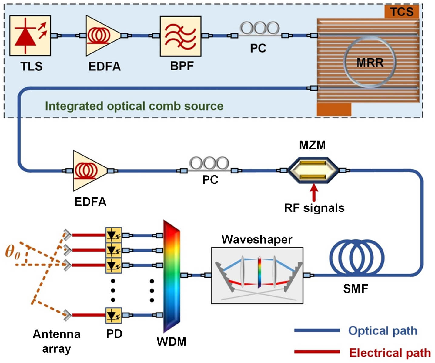
    Fig. 1. Scheme of the proposed TTDL based on an integrated optical comb source. TLS, tunable laser source; EDFA, erbium-doped fiber amplifier; BPF, optical bandpass filter; PC, polarization controller; TCS, temperature controller stage; MZM, Mach–Zehnder modulator; SMF, single-mode fiber; WDM, wavelength division multiplexer; PD, photodetector.
    (a) Schematic illustration of the MRR. Drop-port transmission spectra of the on-chip MRR (b) with a span of 20 nm, showing an FSR of ∼0.4 nm, and (c) with a resonance at ∼1550 nm with full width at half-maximum (FWHM) of ∼1.2 pm (∼150 MHz). (d) Measured and fitted FSR of the MRR. Optical spectra of the generated Kerr comb with a span of (e) 100 nm and (f) 50 nm.
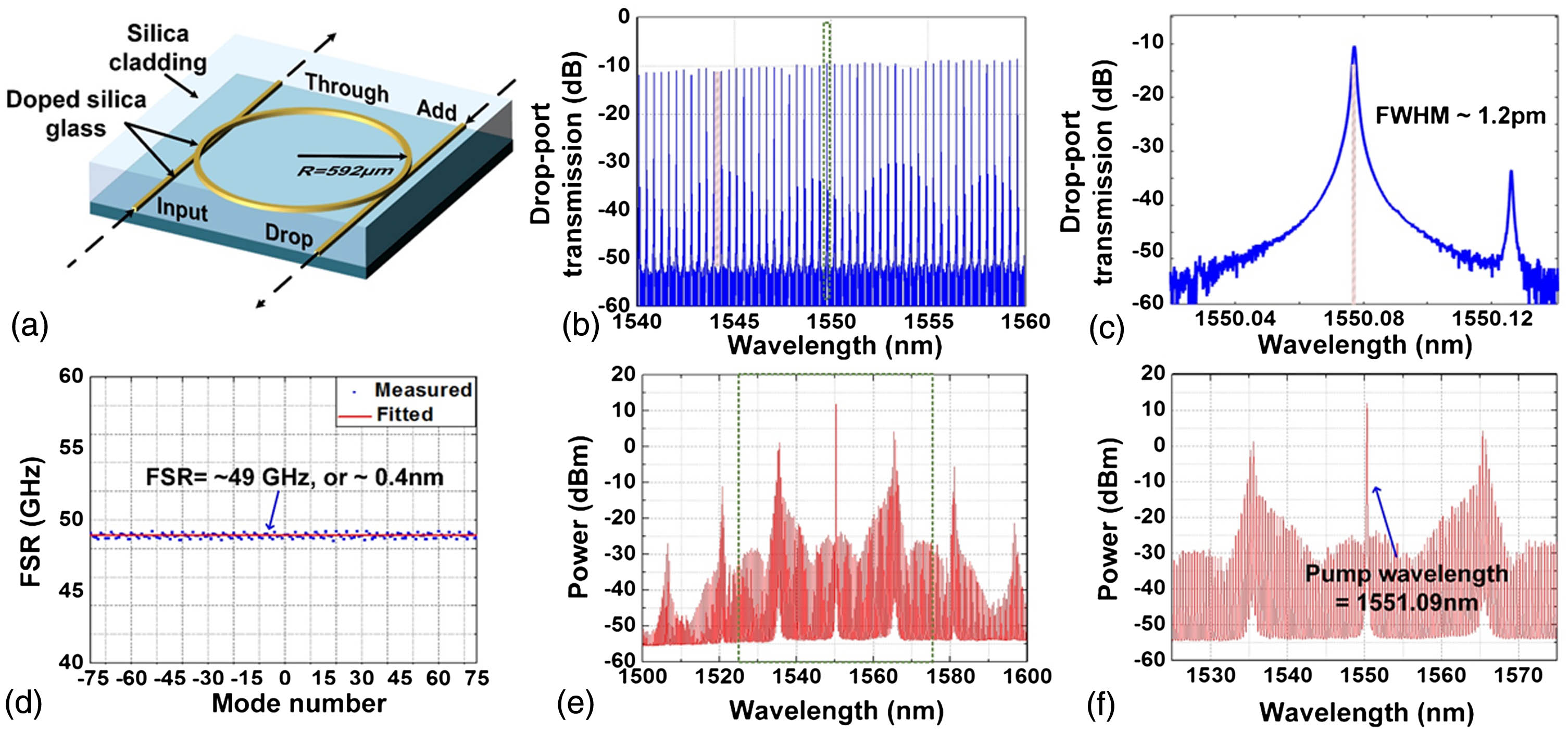
    Fig. 2. (a) Schematic illustration of the MRR. Drop-port transmission spectra of the on-chip MRR (b) with a span of 20 nm, showing an FSR of 0.4  nm, and (c) with a resonance at 1550  nm with full width at half-maximum (FWHM) of 1.2  pm (150  MHz). (d) Measured and fitted FSR of the MRR. Optical spectra of the generated Kerr comb with a span of (e) 100 nm and (f) 50 nm.
    (a) Measured RF phase response of the 81-channel TTDL and (b) corresponding time delays of each channel. The inset shows flat delays over a wide RF range together with the extracted delay errors. (c) Calculated array factors both with and without delay errors. (d) Calculated array factors with generated weights and with uniform weights. (e) Calculated array factors with M varying from 4 to 81. (f) Relationship between the number of radiating elements (M) and the 3 dB beamwidth (θ3 dB).
    Fig. 3. (a) Measured RF phase response of the 81-channel TTDL and (b) corresponding time delays of each channel. The inset shows flat delays over a wide RF range together with the extracted delay errors. (c) Calculated array factors both with and without delay errors. (d) Calculated array factors with generated weights and with uniform weights. (e) Calculated array factors with M varying from 4 to 81. (f) Relationship between the number of radiating elements (M) and the 3 dB beamwidth (θ3dB).
    (a) Calculated AFs of the PAA with m varying from 1 to 15 (M=6) based on the 49 GHz FSR Kerr comb. (b) Calculated AFs of the PAA with m varying from 1 to 7 based on a 200 GHz FSR Kerr comb [49]. (c) Calculated AFs of the PAA with m varying from 1 to 27 based on the 49 GHz FSR Kerr comb. (d) Number of radiating elements (M) and the 3 dB beamwidth (θ3 dB) as a function of m. (e) Beam steering angle θ0 as a function of m. (f) Calculated AFs with RF varying from 2 to 17 GHz.
    Fig. 4. (a) Calculated AFs of the PAA with m varying from 1 to 15 (M=6) based on the 49 GHz FSR Kerr comb. (b) Calculated AFs of the PAA with m varying from 1 to 7 based on a 200 GHz FSR Kerr comb [49]. (c) Calculated AFs of the PAA with m varying from 1 to 27 based on the 49 GHz FSR Kerr comb. (d) Number of radiating elements (M) and the 3 dB beamwidth (θ3dB) as a function of m. (e) Beam steering angle θ0 as a function of m. (f) Calculated AFs with RF varying from 2 to 17 GHz.
    Xingyuan Xu, Jiayang Wu, Thach G. Nguyen, Tania Moein, Sai T. Chu, Brent E. Little, Roberto Morandotti, Arnan Mitchell, David J. Moss. Photonic microwave true time delays for phased array antennas using a 49  GHz FSR integrated optical micro-comb source [Invited][J]. Photonics Research, 2018, 6(5): B30
    Download Citation