Author Affiliations
1Centre for Micro-Photonics, Swinburne University of Technology, Hawthorn, VIC 3122, Australia2ARC Centre of Excellence for Ultrahigh-bandwidth Devices for Optical Systems (CUDOS), RMIT University, Melbourne, VIC 3001, Australia3Department of Physics and Material Science, City University of Hong Kong, Tat Chee Avenue, Hong Kong, China4State Key Laboratory of Transient Optics and Photonics, Xi’an Institute of Optics and Precision Mechanics, Chinese Academy of Sciences, Xi’an 710119, China5INRS-Énergie, Matériaux et Télécommunications, 1650 Boulevard Lionel-Boulet, Varennes, Québec J3X 1S2, Canada6National Research University of Information Technologies, Mechanics and Optics, St. Petersburg, Russia7Institute of Fundamental and Frontier Sciences, University of Electronic Science and Technology of China, Chengdu 610054, Chinashow less
Abstract
We demonstrate significantly improved performance of a microwave true time delay line based on an integrated optical frequency comb source. The broadband micro-comb (over 100 nm wide) features a record low free spectral range (FSR) of 49 GHz, resulting in an unprecedented record high channel number (81 over the C band)—the highest number of channels for an integrated comb source used for microwave signal processing. We theoretically analyze the performance of a phased array antenna and show that this large channel count results in a high angular resolution and wide beam-steering tunable range. This demonstrates the feasibility of our approach as a competitive solution toward implementing integrated photonic true time delays in radar and communications systems.1. INTRODUCTION
In modern radar and communications systems, photonic signal processing has attracted great interest due to its numerous intrinsic advantages, such as broad operation bandwidth, low loss, and strong immunity to electromagnetic interference [1–5]. Photonic microwave true time delay lines (TTDLs), which can introduce multiple progressive time delays, are one of the basic building blocks of microwave photonic systems. Offering intrinsically low loss, ultra-wide operation bandwidth, greatly reduced footprint, and immunity to electromagnetic interference, photonic TTDLs have wide applications for phased array antennas (PAAs), microwave photonic filters, analog-to-digital or digital-to-analog conversion, and arbitrary waveform generation [6–21].
Extensive effort has been devoted to developing diverse methods for TTDLs, including using dispersive elements such as single-mode fiber (SMF) [22], dispersion compensation fiber [23], and fiber Bragg gratings (FBGs) [24,25], slow-light devices based on stimulated Brillouin scattering, integrated resonators [26–28], wavelength conversion coupled with chromatic dispersion [29], and more [30,31]. Further, tunable progressive TTDLs based on a switch-controlled dispersive recirculating loop [32], fast sweeping lasers [33], and dispersion-tunable media [34] have also been investigated.
For PAAs, the number of radiating elements determines the beamwidth, and so to enhance the angular resolution, a large channel number is required for the TTDL. Typically, discrete laser arrays [26,32–34] or FBG arrays [24,25] have been employed for multiple TTDL channels, resulting in a significant increase in system cost and complexity. In turn, this greatly limits the number of channels in practical systems. Other schemes based on optical frequency combs (OFCs) [6] can mitigate this problem, yet many approaches to generating OFCs, such as those based on cascaded electro-optical (EO) modulators [9,35–40] and Fabry–Perot EO modulators [41], require external radio frequency (RF) sources, which still impose considerable cost and complexity to the TTDL.
Sign up for Photonics Research TOC. Get the latest issue of Photonics Research delivered right to you!Sign up now
On the other hand, OFCs generated by high- micro-resonators, termed micro-combs or Kerr combs [42–47], offer a new generation of compact, low-cost, and highly efficient multi-wavelength sources, thus bringing about huge possibilities toward achieving high-performance TTDLs. Their advantages include the potential for a large number of channels (wavelengths) and greatly reduced footprint and complexity, resulting in significantly improved performance for delay-line structure-based microwave photonic systems.
Recently [48,49], we demonstrated photonic microwave TTDLs based on an integrated micro-comb source with a free spectral range (FSR) of 200 GHz, achieving high performance when applied to PAAs in terms of beam resolution and angular tuning range. In this paper, we significantly improve the performance of this device, both in terms of angular resolution and beamwidth, by employing a micro-comb source with a 49 GHz FSR, thus dramatically increasing the available number of channels from 21 to 81 over the -band, which is record high for integrated comb-source-based TTDLs. We experimentally demonstrate an 81-channel true time delay and then calculate the key performance parameters for a phased array antenna based on our device, thus verifying the feasibility and effectiveness of our approach.
2. OPERATION PRINCIPLE
Figure 1 shows a schematic of the microwave TTDL based on an integrated optical Kerr comb source. The TTDL contains two modules: the first generates the optical micro-comb using an integrated micro-ring resonator (MRR), while the second creates replicas of input RF signals at each wavelength, followed by weighting and wavelength-dependent time delays (i.e., induced by the dispersive medium) using standard optical fibers to form the high-channel count TTDL for the phased array antenna.
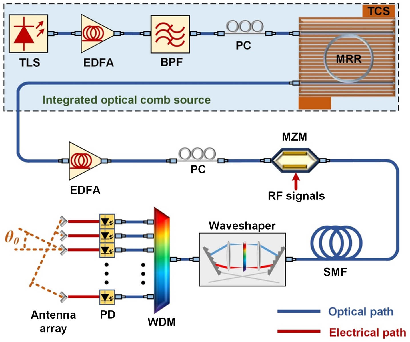
Figure 1.Scheme of the proposed TTDL based on an integrated optical comb source. TLS, tunable laser source; EDFA, erbium-doped fiber amplifier; BPF, optical bandpass filter; PC, polarization controller; TCS, temperature controller stage; MZM, Mach–Zehnder modulator; SMF, single-mode fiber; WDM, wavelength division multiplexer; PD, photodetector.
The MRR used to generate the Kerr optical comb [Fig. 2(a)] was fabricated on a high-index doped silica glass platform using CMOS compatible processes [42]. First, high-index ( at 1550 nm) doped silica glass films were deposited using plasma enhanced chemical vapor deposition (PECVD), then patterned by deep UV photolithography, and subsequently processed via reactive ion etching to form waveguides with exceptionally low surface roughness. Finally, silica ( at 1550 nm) was deposited via PECVD as an upper cladding. Our device architecture used a vertical coupling scheme in which the gap can be controlled via film growth—a more accurate approach than lithographic techniques [50]. Other advantages of our platform for nonlinear optics include ultra-low linear loss (), a relatively high nonlinear parameter (), and, in particular, negligible nonlinear loss up to extremely high intensities () [42–44]. The compact integrated MRR had a radius of with an FSR of , i.e., , as indicated in Figs. 2(b) and 2(d). Although micro-combs with smaller FSRs have been reported with whispering-gallery-mode resonators or SiN MRRs [51,52], our device has the smallest FSR of any micro-comb source that has been used for microwave signal processing. This FSR—a factor of 4 smaller than our previous results [48,49]—enabled up to 4 times the number of channels (as many as 81 channels) over the -band. After packaging the device with fiber pigtails, the total insertion loss was . Because of the ultra-low propagation loss of our platform, the MRR featured a narrow resonance linewidth [Fig. 2(c)] corresponding to a -factor of . To obtain optimal parametric gain, the MRR was designed to feature anomalous dispersion in the -band [53].

Figure 2.(a) Schematic illustration of the MRR. Drop-port transmission spectra of the on-chip MRR (b) with a span of 20 nm, showing an FSR of , and (c) with a resonance at with full width at half-maximum (FWHM) of (). (d) Measured and fitted FSR of the MRR. Optical spectra of the generated Kerr comb with a span of (e) 100 nm and (f) 50 nm.
In the first module, continuous-wave (CW) pump light from a tunable laser source was amplified by an erbium-doped fiber amplifier (EDFA) to pump the on-chip MRR. Before the MRR, a tunable optical bandpass filter and a polarization controller were employed to suppress the amplified spontaneous emission noise and adjust the polarization state, respectively. When the pump wavelength was tuned to one of the resonances of the MRR and the pump power was high enough to provide sufficient parametric gain, parametric oscillation in the MRR occurred, ultimately generating a Kerr optical comb with a high degree of equal line spacing [42,43]. To avoid resonance drift and maintain the wavelength alignment of the resonances to the pump light, the MRR was mounted on a temperature-controlled stage.
In the second module, the generated Kerr comb was directed to a Mach–Zehnder modulator (MZM), where replicas of an input RF signal were produced at each wavelength. The output optical signals from the MZM were delayed by a dispersive SMF, yielding a time delay difference between adjacent channels. Finally, individual channels were manipulated by a waveshaper, separated by a wavelength division multiplexer (WDM), thus achieving a multichannel RF TTDL based on Kerr combs.
We note that integrated dispersive delays, needed for fully integrated beamforming systems, have been achieved recently using promising approaches, including chirped Bragg gratings [54], photonic crystals [55], and low-loss silicon nitride waveguides [56].
In PAA systems, optical signals on selected TTDL channels are separately converted into the electrical domain and then sent to an antenna array to drive the radiating elements. Considering that the antenna array is a uniformly spaced linear array with an element spacing of , the steering angle of the PAA can be given as [57] where is the speed of light in vacuum, and is the time delay difference between adjacent radiating elements. From Eq. (1), one can see that the steering angle can be tuned by adjusting , i.e., changing the length of the dispersive medium or simply selecting every th () TTDL channel as radiating elements. These two approaches for tuning τ offer complementary advantages—either fine tuning steps or a large tuning range, respectively—and so they can be combined to achieve optimized performance for practical applications. In the latter case, , where is the time delay difference between adjacent channels, which is determined jointly by the frequency spacing of the comb source and the dispersion accumulated in the delay line. Thus, the steering angle is given by
The corresponding array factor (AF) of the PAA can be expressed as [57] where is the radiation angle, is the number of radiating elements, and is the wavelength of the RF signals. The angular resolution of the PAA is the minimum angular separation at which two equal targets in the same range can be separated, and is determined by the 3 dB beamwidth that can be approximated [58] as , which in turn greatly decreases with the number of radiating elements (). Our TTDL, based on an integrated optical comb source, provides a large number of radiating elements for beam steering, resulting in a greatly enhanced angular resolution of the PAA. Compared with existing techniques based on discrete laser diode arrays, our approach features a compact and simplified structure, with potentially significantly reduced cost and high performance brought about by the large number of delay channels.
3. EXPERIMENTAL AND THEORETICAL RESULTS
To generate the 49 GHz spacing micro-comb, the pump power was boosted up to 30.5 dBm via an EDFA and the wavelength was swept toward the red side. When the detuning between pump wavelength and MRR resonance became small enough such that the intracavity field reached a threshold value, modulation instability was initiated, and primary combs arose with a spacing of multiple FSRs. As the detuning was further changed, the parametric gain lobes broadened and secondary comb lines with a spacing equal to the FSR of the MRR were generated by both degenerate and non-degenerate four-wave mixing. This finally resulted in a single FSR spaced Kerr optical comb [44,59] [Fig. 2(e)] that was over 100 nm wide. A zoom-in view [Fig. 2(f)] indicates that potentially more than 400 wavelengths were available for the TTDL. For our experiments, however, the wavelength range was limited to the -band because of the waveshaper and EDFA, and so this resulted in 81 usable channels, or wavelengths.
While the spectral profile of our comb was not indicative of operation in the single cavity soliton regime, at the same time the observed stability of the comb spectrum made it clear that we were not operating in the chaotic regime of the Ikeda map [60,61]. In fact, both the shape and stability of our comb, we believe, are indicative of possible operation in multiple soliton states, such as recently reported soliton crystals [62]. Practically speaking, we found that as long as the chaotic states are avoided, the combs generally exhibit sufficient stability to feature low enough intensity noise to allow for their effective use in these applications.
The generated comb served as the multi-wavelength source for the TTDL and since the comb spectrum was stable, a waveshaper could be used to shape the comb lines to generate desired channel weights. The optical power difference between the comb lines could be compensated for via multi-stage spectral shaping combined with optical amplification [20] to meet practical system requirements. Looking to the future, high-conversion-efficiency Kerr combs generated by dark pulses [63] may provide an attractive solution to produce appropriately shaped combs with much higher energy efficiency.
As Fig. 1 shows, the modulated signal after the MZM (EOSPACE) was propagated through of SMF with a dispersion of , corresponding to a time delay of between adjacent wavelength channels. We subsequently employed a waveshaper (Finisar 4000s) as a wavelength division multiplexer to separate these channels and then convert them back into the RF domain for PAA applications, thus achieving a high channel count (up to 81 around the pump wavelength) TTDL with a compact structure.
The RF phase response was characterized by a vector network analyzer [Anritsu 37369A, Fig. 3(a)], in which the channel at the central pump wavelength (channel 40) was set as the reference. The time delays corresponding to the measured phase slopes are shown in Fig. 3(b), in which a time delay step of can be observed. To evaluate the uniformity of the delay steps between adjacent channels, we fit the measured delays with a second-order polynomial function: where , is the channel number, and are the fit coefficients. As Eq. (4) shows, uniform delay steps correspond to linear , while the fit curves (, , ) shown in Fig. 3(b) indicate the appearance of small second-order terms arising from the third-order dispersion (TOD), thus introducing small delay errors in the TTDL (as extracted in the inset). Deviation in the comb wavelength spacing is extremely small (), and so any delay error induced by non-equidistance of the comb lines () is negligible.
Figure 3.(a) Measured RF phase response of the 81-channel TTDL and (b) corresponding time delays of each channel. The inset shows flat delays over a wide RF range together with the extracted delay errors. (c) Calculated array factors both with and without delay errors. (d) Calculated array factors with generated weights and with uniform weights. (e) Calculated array factors with varying from 4 to 81. (f) Relationship between the number of radiating elements () and the 3 dB beamwidth ().
To investigate key performance parameters of the PAA driven by the micro-comb-based TTDL, we calculated the array factors. Since many factors contribute to the performance of the PAA, such as delay errors, imprecision in channel weights, the number of radiating elements, and rapid RF frequency variations, we adopted control variables during the investigation and calculated the AFs by varying only one parameter at a time.
In Fig. 3(c), the AFs are calculated with and without delay errors (uniform weights, , ). As can be seen, the delay errors induced by TOD shift the beam steering angle by 1.54°, and so this must be compensated for when designing the PAA system. We note that TOD compensation in fiber has been widely investigated using many approaches, and in our case this can easily be achieved by programming the phase characteristics of the waveshaper.
In Fig. 3(d), the AFs are calculated with generated weights (inset, where the weights of five comb lines are suppressed for the calculation) and uniform weights (, , , , ). Both of the AFs calculated in this way yield different beam patterns that are useful for specific applications. We note that arbitrary beam patterns can be achieved by shaping the channel weights, as we previously reported [48,49].
In Fig. 3(e), AFs are calculated as increases from 4 to 81 (uniform weights, , , , ), where we see that the corresponding 3 dB beamwidth significantly decreases from 26.8° to 1.2°, matching well with the prediction , as shown in Fig. 3(f). Compared with previous results based on a 200 GHz FSR Kerr comb [49], the much larger channel number provided by the 49 GHz FSR Kerr comb significantly improves beam resolution for the PAA by more than a factor of 4.
To achieve a tunable beam steering angle, every th () wavelength of the TTDL can be selected by using the waveshaper. As well, the time delay () between the radiating elements could be varied with a step size of . As shown in Fig. 4(a), with six radiating elements (), as varies from 1 to 15, a large tuning range from to 72.9° can be achieved. We note that tuning by selecting every th wavelength is practical in our case because of the large number of channels. The beamwidth () and steering angle tuning range () represent a trade-off in practical systems. To reflect the relationships between those parameters, in Figs. 4(b)–4(e) we present AFs of PAAs with varying and , where . Considering the practical requirements for beam steering, can be set to 3 at least, and thus for the 21-channel PAA based on the 200 GHz FSR Kerr comb [49], could reach 7 at most, while for the 81-channel PAA based on the 49 GHz FSR Kerr comb, could reach as much as 27. Figures 4(b) and 4(c) show the corresponding , , and as a function of , respectively. As can be seen, on the one hand, the 49 GHz FSR Kerr comb enables a much larger as varies, thus leading to a significantly smaller and greatly enhanced angular resolution [Fig. 4(d)]. On the other hand, finer tuning steps (from 1.0° to 14.7°) as well as a larger tuning range (142.7°) of the beam steering angle are available due to the larger [Fig. 4(e)].
Figure 4.(a) Calculated AFs of the PAA with varying from 1 to 15 () based on the 49 GHz FSR Kerr comb. (b) Calculated AFs of the PAA with varying from 1 to 7 based on a 200 GHz FSR Kerr comb [49]. (c) Calculated AFs of the PAA with varying from 1 to 27 based on the 49 GHz FSR Kerr comb. (d) Number of radiating elements () and the 3 dB beamwidth () as a function of . (e) Beam steering angle as a function of . (f) Calculated AFs with RF varying from 2 to 17 GHz.
Given the practical requirements in beamwidth and steering angle tuning range, optimized sets of and can be clearly identified from these calculations. Further, the beam steering angle can be improved in terms of both tuning step and tuning range by employing dispersion tunable media [32,34] in addition to varying the number of TTDL channels.
Moreover, the PAA can also achieve a wide instantaneous RF bandwidth without beam squint (variation in beam steering angle with RF). Based on the proposed TTDL, as indicated in Fig. 4(f), the beam steering angle remains 20.7°, while the RF varies from 2 to 17 GHz (with uniform weights, , , , ). As a result, because of our large number of channels, the PAA features greatly enhanced angular resolution, large instantaneous bandwidth, and a wide tunable range of the beam steering angle.
4. CONCLUSION
We demonstrate a high channel count (81 over the -band) TTDL based on an integrated optical frequency comb source. A broadband Kerr comb with a large number of comb lines was generated by an on-chip MRR with an FSR of 49 GHz, which was employed as a high-quality multi-wavelength source for the TTDL. Compared with those of traditional approaches, the size, complexity, and, ultimately, the cost of the system can be greatly reduced. The large channel number of the TTDL resulted in a PAA with a calculated high angular resolution and wide tuning range of the beam steering angle. The enhancement in performance matches well with theory, confirming the feasibility of our approach as a promising solution toward implementing highly reconfigurable TTDLs for microwave photonic signal processing functions.
References
[1] J. Capmany, D. Novak. Microwave photonics combines two worlds. Nat. Photonics, 1, 319-330(2007).
[2] M. Ferrera, C. Reimer, A. Pasquazi, M. Peccianti, M. Clerici, L. Caspani, S. T. Chu, B. E. Little, R. Morandotti, D. J. Moss. CMOS compatible integrated all-optical radio frequency spectrum analyzer. Opt. Express, 22, 21488-21498(2014).
[3] B. Corcoran, T. D. Vo, M. D. Pelusi, C. Monat, D. X. Xu, A. Densmore, R. B. Ma, S. Janz, D. J. Moss, B. J. Eggleton. Silicon nanowire based radio-frequency spectrum analyzer. Opt. Express, 18, 20190-20200(2010).
[4] M. Pelusi, F. Luan, T. D. Vo, M. R. E. Lamont, S. J. Madden, D. A. Bulla, D. Y. Choi, B. Luther-Davies, B. J. Eggleton. Photonic-chip-based radio-frequency spectrum analyser with terahertz bandwidth. Nat. Photonics, 3, 139-143(2009).
[5] A. Pasquazi, M. Peccianti, B. E. Little, S. T. Chu, D. J. Moss, R. Morandotti. Stable, dual mode, high repetition rate mode-locked laser based on a microring resonator. Opt. Express, 20, 27355-27362(2012).
[6] J. P. Yao. Microwave photonics. J. Lightwave Technol., 27, 314-335(2009).
[7] R. C. Williamson, R. D. Esman. RF photonics. J. Lightwave Technol., 26, 1145-1153(2008).
[8] A. J. Seeds. Microwave photonics. IEEE Trans. Microwave Theory, 50, 877-887(2002).
[9] K. Xu, R. X. Wang, Y. T. Dai, F. F. Yin, J. Q. Li, Y. F. Ji, J. T. Lin. Microwave photonics: radio-over-fiber links, systems, and applications. Photon. Res., 2, B54-B63(2014).
[10] R. A. Minasian. Ultra-wideband and adaptive photonic signal processing of microwave signals. IEEE J. Quantum Electron., 52, 0600813(2016).
[11] J. Capmany, B. Ortega, D. Pastor. A tutorial on microwave photonic filters. J. Lightwave Technol., 24, 201-229(2006).
[12] T. G. Nguyen, M. Shoeiby, S. T. Chu, B. E. Little, R. Morandotti, A. Mitchell, D. J. Moss. Integrated frequency comb source based Hilbert transformer for wideband microwave photonic phase analysis. Opt. Express, 23, 22087-22097(2015).
[13] J. Wu, X. Xu, T. G. Nguyen, S. T. Chu, B. E. Little, A. Mitchell, R. Morandotti, D. J. Moss. Harnessing optical micro-combs for microwave photonics.
[14] A. Malacarne, R. Ashrafi, Y. Park, J. Azana. Reconfigurable optical differential phase-shift-keying pattern recognition based on incoherent photonic processing. Opt. Lett., 36, 4290-4292(2011).
[15] Y. Park, M. H. Asghari, R. Helsten, J. Azana. Implementation of broadband microwave arbitrary-order time differential operators using a reconfigurable incoherent photonic processor. IEEE Photon. J., 2, 1040-1050(2010).
[16] J. Azana, C. Madsen, K. Takiguchi, G. Cincotti. Guest editorial—optical signal processing. J. Lightwave Technol., 24, 2484-2486(2006).
[17] S. Mansoori, A. Mitchell. RF transversal filter using an AOTF. IEEE Photon. Technol. Lett., 16, 879-881(2004).
[18] X. Q. Zhu, F. Y. Chen, H. F. Peng, Z. Y. Chen. Novel programmable microwave photonic filter with arbitrary filtering shape and linear phase. Opt. Express, 25, 9232-9243(2017).
[19] A. Ortigosa-Blanch, J. Mora, J. Capmany, B. Ortega, D. Pastor. Tunable radio-frequency photonic filter based on an actively mode-locked fiber laser. Opt. Lett., 31, 709-711(2006).
[20] X. X. Xue, Y. Xuan, H. J. Kim, J. Wang, D. E. Leaird, M. H. Qi, A. M. Weiner. Programmable single-bandpass photonic RF filter based on Kerr comb from a micro-ring. J. Lightwave Technol., 32, 3557-3565(2014).
[21] E. Hamidi, D. E. Leaird, A. M. Weiner. Tunable programmable microwave photonic filters based on an optical frequency comb. IEEE Trans. Microwave Theory, 58, 3269-3278(2010).
[22] X. W. Ye, F. Z. Zhang, S. L. Pan. Optical true time delay unit for multi-beamforming. Opt. Express, 23, 10002-10008(2015).
[23] D. H. Yang, W. P. Lin. Phased-array beam steering using optical true time delay technique. Opt. Commun., 350, 90-96(2015).
[24] Y. Q. Liu, J. P. Yao, J. L. Yang. Wideband true-time-delay unit for phased array beamforming using discrete-chirped fiber grating prism. Opt. Commun., 207, 177-187(2002).
[25] J. L. Cruz, B. Ortega, M. V. Andres, B. Gimeno, D. Pastor, J. Capmany, L. Dong. Chirped fibre Bragg gratings for phased-array antennas. Electron. Lett., 33, 545-546(1997).
[26] S. Chin, L. Thevenaz, J. Sancho, S. Sales, J. Capmany, P. Berger, J. Bourderionnet, D. Dolfi. Broadband true time delay for microwave signal processing, using slow light based on stimulated Brillouin scattering in optical fibers. Opt. Express, 18, 22599-22613(2010).
[27] K. Y. Song, M. G. Herraez, L. Thevenaz. Observation of pulse delaying and advancement in optical fibers using stimulated Brillouin scattering. Opt. Express, 13, 82-88(2005).
[28] P. A. Morton, J. B. Khurgin. Microwave photonic delay line with separate tuning of the optical carrier. IEEE Photon. Technol. Lett., 21, 1686-1688(2009).
[29] O. F. Yilmaz, L. Yaron, S. Khaleghi, M. R. Chitgarha, M. Tur, A. Willner. True time delays using conversion/dispersion with flat magnitude response for wideband analog RF signals. Opt. Express, 20, 8219-8227(2012).
[30] J. Mork, R. Kjaer, M. van der Poel, K. Yvind. Slow light in a semiconductor waveguide at gigahertz frequencies. Opt. Express, 13, 8136-8145(2005).
[31] H. Su, P. Kondratko, S. L. Chuang. Variable optical delay using population oscillation and four-wave-mixing in semiconductor optical amplifiers. Opt. Express, 14, 4800-4807(2006).
[32] J. J. Zhang, J. P. Yao. Photonic true-time delay beamforming using a switch-controlled wavelength-dependent recirculating loop. J. Lightwave Technol., 34, 3923-3929(2016).
[33] L. H. Zhang, M. Li, N. N. Shi, X. Y. Zhu, S. Q. Sun, J. Tang, W. Li, N. H. Zhu. Photonic true time delay beamforming technique with ultra-fast beam scanning. Opt. Express, 25, 14524-14532(2017).
[34] Y. Q. Liu, J. L. Yang, J. P. Yao. Continuous true-time-delay beamforming for phased array antenna using a tunable chirped fiber grating delay line. IEEE Photon. Technol. Lett., 14, 1172-1174(2002).
[35] R. Wu, V. R. Supradeepa, C. M. Long, D. E. Leaird, A. M. Weiner. Generation of very flat optical frequency combs from continuous-wave lasers using cascaded intensity and phase modulators driven by tailored radio frequency waveforms. Opt. Lett., 35, 3234-3236(2010).
[36] J. Dai, X. Y. Xu, Z. L. Wu, Y. T. Dai, F. F. Yin, Y. Zhou, J. Q. Li, K. Xu. Self-oscillating optical frequency comb generator based on an optoelectronic oscillator employing cascaded modulators. Opt. Express, 23, 30014-30019(2015).
[37] C. H. Chen, C. He, D. Zhu, R. H. Guo, F. Z. Zhang, S. L. Pan. Generation of a flat optical frequency comb based on a cascaded polarization modulator and phase modulator. Opt. Lett., 38, 3137-3139(2013).
[38] R. Wu, V. Torres-Company, D. E. Leaird, A. M. Weiner. Supercontinuum-based 10-GHz flat-topped optical frequency comb generation. Opt. Express, 21, 6045-6052(2013).
[39] A. J. Metcalf, V. Torres-Company, D. E. Leaird, A. M. Weiner. High-power broadly tunable electro-optic frequency comb generator. IEEE J. Sel. Top. Quantum Electron., 19, 231-236(2013).
[40] W. Z. Li, J. P. Yao. Optical frequency comb generation based on repeated frequency shifting using two Mach-Zehnder modulators and an asymmetric Mach-Zehnder interferometer. Opt. Express, 17, 23712-23718(2009).
[41] T. Saitoh, M. Kourogi, M. Ohtsu. A waveguide-type optical-frequency comb generator. IEEE Photon. Technol. Lett., 7, 197-199(1995).
[42] L. Razzari, D. Duchesne, M. Ferrera, R. Morandotti, S. Chu, B. E. Little, D. J. Moss. CMOS-compatible integrated optical hyper-parametric oscillator. Nat. Photonics, 4, 41-45(2010).
[43] D. J. Moss, R. Morandotti, A. L. Gaeta, M. Lipson. New CMOS-compatible platforms based on silicon nitride and Hydex for nonlinear optics. Nat. Photonics, 7, 597-607(2013).
[44] A. Pasquazi, M. Pecciantia, L. Razzari, R. Morandotti, D. J. Moss, S. Coen, M. Erkintalo, T. Hansson, S. Wabnitz, P. Del Haye, A. M. Weiner. Micro-combs: a novel generation of optical sources. Phys. Rep., 729, 1-81(2018).
[45] M. Peccianti, M. Ferrera, L. Razzari, R. Morandotti, B. E. Little, S. T. Chu, D. J. Moss. Sub-picosecond optical pulse compression via an integrated nonlinear chirper. Opt. Express, 18, 7625-7633(2010).
[46] D. Duchesne, M. Peccianti, M. Lamont, M. Ferrera, L. Razzari, F. Légaré, R. Morandotti, S. Chu, B. E. Little, D. J. Moss. Supercontinuum generation in a high index doped silica glass spiral waveguide. Opt. Express, 18, 923-930(2010).
[47] A. Pasquazi, Y. Park, J. Azaña, F. Légaré, R. Morandotti, B. E. Little, S. T. Chu, D. J. Moss. Efficient wavelength conversion and net parametric gain via four wave mixing in a high index doped silica waveguide. Opt. Express, 18, 7634-7641(2010).
[48] X. Xu, J. Wu, M. Shoeiby, T. G. Nguyen, S. T. Chu, B. E. Little, R. Morandotti, A. Mitchell, D. J. Moss. Microwave photonic all-optical differentiator based on an integrated frequency comb source. APL Photon., 2, 096104(2017).
[49] X. Xu, J. Wu, T. G. Nguyen, T. Moein, S. T. Chu, B. E. Little, R. Morandotti, A. Mitchell, D. J. Moss. Advanced RF and microwave functions based on an integrated optical frequency comb source. Opt. Express, 26, 2569-2583(2018).
[50] J. Wu, T. Moein, X. Xu, G. Ren, A. Mitchell, D. J. Moss. Micro-ring resonator quality factor enhancement via an integrated Fabry-Perot cavity. APL Photon., 2, 056103(2017).
[51] W. Liang, D. Eliyahu, V. S. Ilchenko, A. A. Savchenkov, A. B. Matsko, D. Seidel, L. Maleki. High spectral purity Kerr frequency comb radio frequency photonic oscillator. Nat. Commun., 6, 7957(2015).
[52] A. R. Johnson, Y. Okawachi, J. S. Levy, J. Cardenas, K. Saha, M. Lipson, A. L. Gaeta. Chip-based frequency combs with sub-100 GHz repetition rates. Opt. Lett., 37, 875-877(2012).
[53] W. Q. Wang, S. T. Chu, B. E. Little, A. Pasquazi, Y. S. Wang, L. R. Wang, W. F. Zhang, L. Wang, X. H. Hu, G. X. Wang, H. Hu, Y. L. Su, F. T. Li, Y. S. Liu, W. Zhao. Dual-pump Kerr micro-cavity optical frequency comb with varying FSR spacing. Sci. Rep., 6, 28501(2016).
[54] A. Strain, M. Sorel. Design and fabrication of integrated chirped Bragg gratings for on-chip dispersion control. IEEE J. Quantum Electron., 46, 774-782(2010).
[55] E. Sahin, K. J. A. Ooi, C. E. Png, D. T. H. Tan. Large, scalable dispersion engineering using cladding-modulated Bragg gratings on a silicon chip. Appl. Phys. Lett., 110, 161113(2017).
[56] B. Stern, X. C. Ji, A. Dutt, M. Lipson. Compact narrow-linewidth integrated laser based on a low-loss silicon nitride ring resonator. Opt. Lett., 42, 4541-4544(2017).
[57] M. Longbrake. True time-delay beamsteering for radar. IEEE National Aerospace and Electronics Conference (NAECON), 246-249(2012).
[58] M. I. Skolnik. Introduction to Radar Systems(2001).
[59] T. Herr, K. Hartinger, J. Riemensberger, C. Y. Wang, E. Gavartin, R. Holzwarth, M. L. Gorodetsky, T. J. Kippenberg. Universal formation dynamics and noise of Kerr-frequency combs in microresonators. Nat. Photonics, 6, 480-487(2012).
[60] Y. K. Chembo, C. R. Menyuk. Spatiotemporal Lugiato-Lefever formalism for Kerr-comb generation in whispering-gallery-mode resonators. Phys. Rev. A, 87, 053852(2013).
[61] S. Coen, H. G. Randle, T. Sylvestre, M. Erkintalo. Modeling of octave-spanning Kerr frequency combs using a generalized mean-field Lugiato-Lefever model. Opt. Lett., 38, 37-39(2013).
[62] D. C. Cole, E. S. Lamb, P. Del’Haye, S. A. Diddams, S. B. Papp. Soliton crystals in Kerr resonators. Nat. Photonics, 11, 671-676(2017).
[63] X. X. Xue, Y. Xuan, Y. Liu, P. H. Wang, S. Chen, J. Wang, D. E. Leaird, M. H. Qi, A. M. Weiner. Mode-locked dark pulse Kerr combs in normal-dispersion microresonators. Nat. Photonics, 9, 594-600(2015).


