• Photonics Research
  • Vol. 9, Issue 4, B135 (2021)
Yihao Xu1, Xianzhe Zhang2, Yun Fu2、3, and Yongmin Liu1、2、*
Author Affiliations
  • 1Department of Mechanical and Industrial Engineering, Northeastern University, Boston, Massachusetts 02115, USA
  • 2Department of Electrical and Computer Engineering, Northeastern University, Boston, Massachusetts 02115, USA
  • 3Khoury College of Computer Science, Northeastern University, Boston, Massachusetts 02115, USA
  • show less
    DOI: 10.1364/PRJ.417693 Cite this Article Set citation alerts
    Yihao Xu, Xianzhe Zhang, Yun Fu, Yongmin Liu. Interfacing photonics with artificial intelligence: an innovative design strategy for photonic structures and devices based on artificial neural networks[J]. Photonics Research, 2021, 9(4): B135 Copy Citation Text show less
    (a) Illustration of a biological neuron. (b) FCLs-based neural network, in which all neurons in adjacent layers are connected. (c) Three widely used activation functions: Sigmoid, tanh, and ReLU.
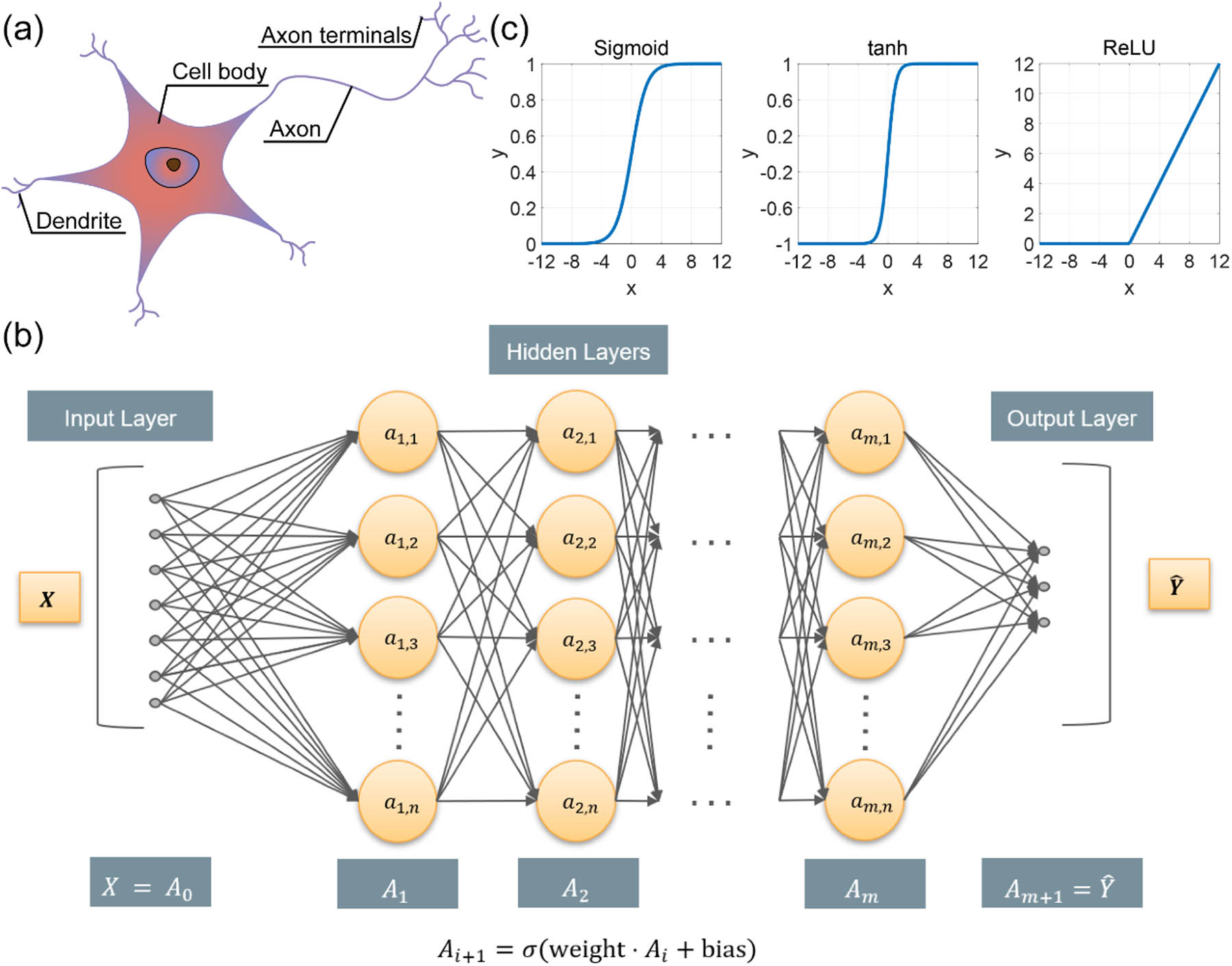
    Fig. 1. (a) Illustration of a biological neuron. (b) FCLs-based neural network, in which all neurons in adjacent layers are connected. (c) Three widely used activation functions: Sigmoid, tanh, and ReLU.
    (a) Top: Schematic of the tandem neural network and SiO2 and Si3O4 multilayers. Bottom: Two examples of target spectra (blue solid lines) and simulated spectra of retrieved structures (green dashed lines). The target spectra are in a Gaussian shape. (b) Left: Predicted (open circles) extinction cross section of the electric dipole (red) and magnetic dipole (black) of core-shell nanoparticles. The solid lines are target responses. Right: Simulated extinction spectra and the corresponding electric field distribution of core-shell nanoparticles. (c) Top: Simulation result and inverse design prediction of the scattering cross section of core-shell nanoparticles. Bottom: Runtime comparison between the conventional method and neural network. (d) Top: A multilayer structure composed of Si3N4 and graphene. Bottom: Optical response of the designed nanostructures (with either low/near-unity absorbance in graphene) under the excitation of s-polarized light. (a) is reproduced from Ref. [46] with permission; (b) is reproduced from Ref. [47] with permission; (c) is reproduced from Ref. [38] with permission; (d) is reproduced from Ref. [48] with permission.
    Fig. 2. (a) Top: Schematic of the tandem neural network and SiO2 and Si3O4 multilayers. Bottom: Two examples of target spectra (blue solid lines) and simulated spectra of retrieved structures (green dashed lines). The target spectra are in a Gaussian shape. (b) Left: Predicted (open circles) extinction cross section of the electric dipole (red) and magnetic dipole (black) of core-shell nanoparticles. The solid lines are target responses. Right: Simulated extinction spectra and the corresponding electric field distribution of core-shell nanoparticles. (c) Top: Simulation result and inverse design prediction of the scattering cross section of core-shell nanoparticles. Bottom: Runtime comparison between the conventional method and neural network. (d) Top: A multilayer structure composed of Si3N4 and graphene. Bottom: Optical response of the designed nanostructures (with either low/near-unity absorbance in graphene) under the excitation of s-polarized light. (a) is reproduced from Ref. [46] with permission; (b) is reproduced from Ref. [47] with permission; (c) is reproduced from Ref. [38] with permission; (d) is reproduced from Ref. [48] with permission.
    (a) Left: Schematic illustration of the metasurface, the unit cell, and matrix encoding method. Right: Predicted S-parameter and absorptivity with the REACTIVE method. (b) Illustration of the neural network architecture consisting of BaseNet and TransferNet. (c) The trend of spectrum error when n layers are transferred to the TransferNet and the predicted transmission spectra for two examples. (a) is reproduced from Ref. [39] with permission; (b) and (c) are reproduced from Ref. [49] with permission.
    Fig. 3. (a) Left: Schematic illustration of the metasurface, the unit cell, and matrix encoding method. Right: Predicted S-parameter and absorptivity with the REACTIVE method. (b) Illustration of the neural network architecture consisting of BaseNet and TransferNet. (c) The trend of spectrum error when n layers are transferred to the TransferNet and the predicted transmission spectra for two examples. (a) is reproduced from Ref. [39] with permission; (b) and (c) are reproduced from Ref. [49] with permission.
    (a) Left: Architecture of the proposed neural network for nonlinear layers. Right: Predicted, simulated, and measured transmission spectra of two gold nanostructures under different polarization conditions. (b) Left: Illustrations of MANN used for reconstruction of 3D vectorial field. Right: Experimental approach and characterizations of 3D vectorial holography based on a vectorial hologram. (c) Left: Schematic of a deep-learning-enabled self-adaptive metasurface cloak. Right: Demonstration of the self-adaptive cloak response subject to random backgrounds and incidence with varied angles and frequencies. (a) is reproduced from Ref. [54] with permission; (b) is reproduced from Ref. [63] with permission; (c) is reproduced from Ref. [64] with permission.
    Fig. 4. (a) Left: Architecture of the proposed neural network for nonlinear layers. Right: Predicted, simulated, and measured transmission spectra of two gold nanostructures under different polarization conditions. (b) Left: Illustrations of MANN used for reconstruction of 3D vectorial field. Right: Experimental approach and characterizations of 3D vectorial holography based on a vectorial hologram. (c) Left: Schematic of a deep-learning-enabled self-adaptive metasurface cloak. Right: Demonstration of the self-adaptive cloak response subject to random backgrounds and incidence with varied angles and frequencies. (a) is reproduced from Ref. [54] with permission; (b) is reproduced from Ref. [63] with permission; (c) is reproduced from Ref. [64] with permission.
    (a) Schematic of the convolution operation, in which the filters map the subarea in the input image to a single value in the output image. (b) Schematic of the pooling operation, in which the subarea in the input image is pooled into a single value in the output according to the maximum or mean value. (c) The workflow of a conventional CNN. The input images pass through several CNNs, and then the extracted features are passed into the FCLs to predict the response (e.g., transmission, reflection, and absorption spectra).
    Fig. 5. (a) Schematic of the convolution operation, in which the filters map the subarea in the input image to a single value in the output image. (b) Schematic of the pooling operation, in which the subarea in the input image is pooled into a single value in the output according to the maximum or mean value. (c) The workflow of a conventional CNN. The input images pass through several CNNs, and then the extracted features are passed into the FCLs to predict the response (e.g., transmission, reflection, and absorption spectra).
    (a) Top: Examples of cDCGAN-suggested images and the simulation results. Bottom: Entirely new structures suggested by the cDCGAN for desired spectra. (b) Top: The proposed deep generative model for metamaterial design, which consists of the prediction, recognition, and generation models. Bottom: Evaluation of the proposed model. The desired spectra either generated with user-defined function or simulated from an existing structure are plotted in the first column. The reconstructed structures with the simulated spectra are plotted in the second and third columns. (c) Left: Flowchart of the VAE-ES framework. Right: Test results of designed photonic structures from the proposed model and the simulated spectra. (a) is reproduced from Ref. [69] with permission; (b) is reproduced from Ref. [41] with permission; (c) is reproduced from Ref. [79] with permission.
    Fig. 6. (a) Top: Examples of cDCGAN-suggested images and the simulation results. Bottom: Entirely new structures suggested by the cDCGAN for desired spectra. (b) Top: The proposed deep generative model for metamaterial design, which consists of the prediction, recognition, and generation models. Bottom: Evaluation of the proposed model. The desired spectra either generated with user-defined function or simulated from an existing structure are plotted in the first column. The reconstructed structures with the simulated spectra are plotted in the second and third columns. (c) Left: Flowchart of the VAE-ES framework. Right: Test results of designed photonic structures from the proposed model and the simulated spectra. (a) is reproduced from Ref. [69] with permission; (b) is reproduced from Ref. [41] with permission; (c) is reproduced from Ref. [79] with permission.
    (a) Left: One example of 1-bit coding elements with regular phase differences. Right: Comparison of the simulated and measured results of the dual- and triple-beam coding metasurfaces. (b) Schematic of the proposed 3D CNN model to characterize the near-field and far-field properties of arbitrary dielectric and plasmonic nanostructures. (c) Left: Sketch of the nanostructure geometry and the 1D CNN-based ANNs. Right: Training convergence and readout accuracy of the ANNs. (d) Left: The workflow of designing the DMD pattern for light control through scattering media with ANNs. Right: The structures of the FCLs-based single-layer neural network and the CNNs, together with the simulated and measured results for the focusing effect. (a) is reproduced from Ref. [80] with permission; (b) is reproduced from Ref. [81] with permission; (c) is reproduced from Ref. [86] with permission; (d) is reproduced from Ref. [87] with permission.
    Fig. 7. (a) Left: One example of 1-bit coding elements with regular phase differences. Right: Comparison of the simulated and measured results of the dual- and triple-beam coding metasurfaces. (b) Schematic of the proposed 3D CNN model to characterize the near-field and far-field properties of arbitrary dielectric and plasmonic nanostructures. (c) Left: Sketch of the nanostructure geometry and the 1D CNN-based ANNs. Right: Training convergence and readout accuracy of the ANNs. (d) Left: The workflow of designing the DMD pattern for light control through scattering media with ANNs. Right: The structures of the FCLs-based single-layer neural network and the CNNs, together with the simulated and measured results for the focusing effect. (a) is reproduced from Ref. [80] with permission; (b) is reproduced from Ref. [81] with permission; (c) is reproduced from Ref. [86] with permission; (d) is reproduced from Ref. [87] with permission.
    (a) Left: Illustration of meta-molecules. Right: Fabricated samples and the measured and simulated results of polarization conversion. (b) Top: Schematic of a silicon metagrating that deflects light to a certain angle. Bottom: The proposed conditional GLOnet for metagrating optimization. (c) Top: Schematic of structure refinement and filtering for the high-efficiency thermal emitter. Bottom: The efficiency, emissivity, and normalized emission of the well-optimized thermal emitter. (d) Top: Illustration of the unit cell consisting of three metallic patches connected via PIN diodes and a photograph of the fabricated metasurface. Bottom: Experimental results for reconstructing human body imaging. (a) is reproduced from Ref. [95] with permission; (b) is reproduced from Ref. [100] with permission; (c) is reproduced from Ref. [42] with permission; (d) is reproduced from Ref. [104] with permission.
    Fig. 8. (a) Left: Illustration of meta-molecules. Right: Fabricated samples and the measured and simulated results of polarization conversion. (b) Top: Schematic of a silicon metagrating that deflects light to a certain angle. Bottom: The proposed conditional GLOnet for metagrating optimization. (c) Top: Schematic of structure refinement and filtering for the high-efficiency thermal emitter. Bottom: The efficiency, emissivity, and normalized emission of the well-optimized thermal emitter. (d) Top: Illustration of the unit cell consisting of three metallic patches connected via PIN diodes and a photograph of the fabricated metasurface. Bottom: Experimental results for reconstructing human body imaging. (a) is reproduced from Ref. [95] with permission; (b) is reproduced from Ref. [100] with permission; (c) is reproduced from Ref. [42] with permission; (d) is reproduced from Ref. [104] with permission.
    (a) Top: Comparison between the all-optical D2NN and a conventional ANN. Bottom: Measured performance of the classifier for handwritten digits and fashion products. (b) Top: Sketch of the optical logic operations by a diffractive neural network. Bottom: Experiment setup and measured results of three basic logic operations on the fabricated metasurface. (a) is reproduced from Ref. [118] with permission; (b) is reproduced from Ref. [119] with permission.
    Fig. 9. (a) Top: Comparison between the all-optical D2NN and a conventional ANN. Bottom: Measured performance of the classifier for handwritten digits and fashion products. (b) Top: Sketch of the optical logic operations by a diffractive neural network. Bottom: Experiment setup and measured results of three basic logic operations on the fabricated metasurface. (a) is reproduced from Ref. [118] with permission; (b) is reproduced from Ref. [119] with permission.
    Yihao Xu, Xianzhe Zhang, Yun Fu, Yongmin Liu. Interfacing photonics with artificial intelligence: an innovative design strategy for photonic structures and devices based on artificial neural networks[J]. Photonics Research, 2021, 9(4): B135
    Download Citation