• Infrared and Laser Engineering
  • Vol. 50, Issue 12, 20210150 (2021)
Wenlu Guan1、2、3, Fengfu Tan1、3, Zaihong Hou1、2、3, Laian Qin1、3, Feng He1、3, Silong Zhang1、3, and Yi Wu1、2、3
Author Affiliations
  • 1Key Laboratory of Atmospheric Optics, Anhui Institute of Optics and Fine Mechanics, Hefei Institutes of Physical Science, Chinese Academy of Sciences, Hefei 230031, China
  • 2University of Science and Technology of China, Hefei 230026, China
  • 3Advanced Laser Technology Laboratory of Anhui Province, Hefei 230037, China
  • show less
    DOI: 10.3788/IRLA20210150 Cite this Article
    Wenlu Guan, Fengfu Tan, Zaihong Hou, Laian Qin, Feng He, Silong Zhang, Yi Wu. Design of scattering sampling attenuation unit for detector array target[J]. Infrared and Laser Engineering, 2021, 50(12): 20210150 Copy Citation Text show less
    Schematic diagram of BTDF geometry
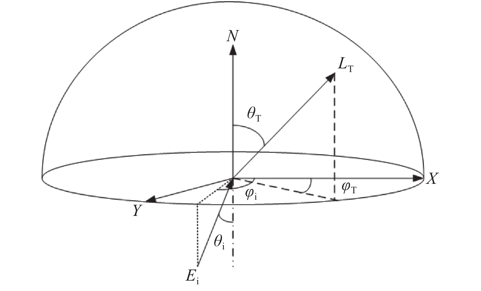
    Fig. 1. Schematic diagram of BTDF geometry
    Distribution characteristics of transmission and scattering angle. (a) Ground glass; (b) Engineering diffuser
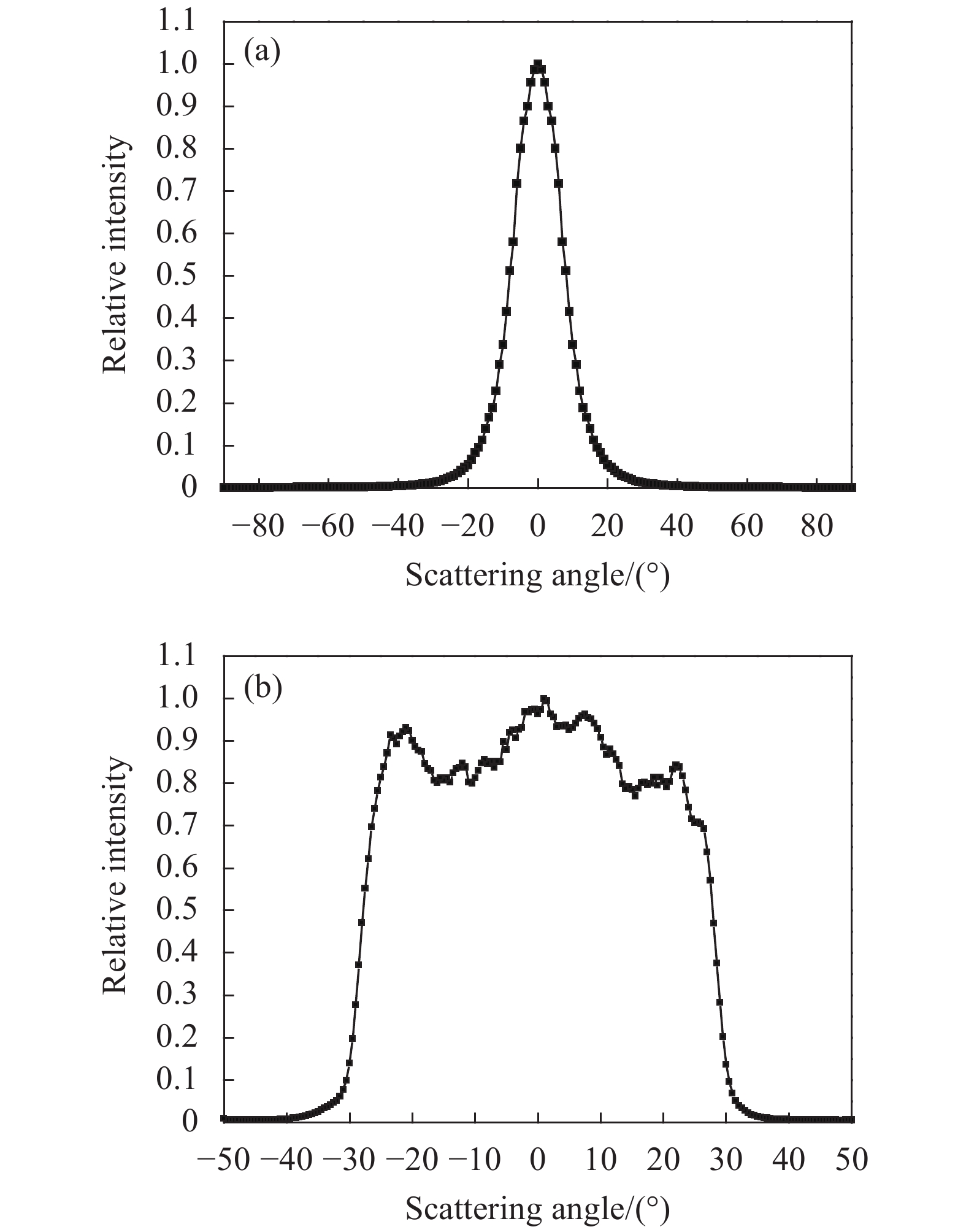
    Fig. 2. Distribution characteristics of transmission and scattering angle. (a) Ground glass; (b) Engineering diffuser
    Structure of scattering sampling attenuation unit
    Fig. 3. Structure of scattering sampling attenuation unit
    Comparison of the simulation results of the scattering angle characteristics of transmitted materials. (a) Ground glass; (b) Engineering diffuser
    Fig. 4. Comparison of the simulation results of the scattering angle characteristics of transmitted materials. (a) Ground glass; (b) Engineering diffuser
    Three-dimensional spatial distribution of the emitted light from the combined sampling attenuation structure
    Fig. 5. Three-dimensional spatial distribution of the emitted light from the combined sampling attenuation structure
    Experimental optical path diagram of transmission and scattering characteristics of sampling materials
    Fig. 6. Experimental optical path diagram of transmission and scattering characteristics of sampling materials
    Grid processing of experimental spots. (a) Acquired spot image; (b) Gridded spot image
    Fig. 7. Grid processing of experimental spots. (a) Acquired spot image; (b) Gridded spot image
    Comparison of simulation and experiment of transmitted scattered light distribution. (a) Single piece of ground glass; (b) Combin-ation of ground glass and engineering diffuser
    Fig. 8. Comparison of simulation and experiment of transmitted scattered light distribution. (a) Single piece of ground glass; (b) Combin-ation of ground glass and engineering diffuser
    Response linearity of combined scattering sampling attenuation structure
    Fig. 9. Response linearity of combined scattering sampling attenuation structure
    MaterialsPower density/W·cm−2Irradiation time/sDamaged condition
    Ground glass2 00020Undamaged
    Engineering diffuser2 0001damaged
    Ground glass + engineering diffuser (d=0.5 mm) 2 0008Damaged
    Ground glass + engineering diffuser (d=1 mm) 2 00012Damaged
    Ground glass + engineering diffuser (d=1.5 mm) 2 00020Undamaged
    Ground glass + engineering diffuser (d=2 mm) 2 00020Undamaged
    Ground glass + engineering diffuser (d=2.5 mm) 2 00020Undamaged
    Table 1. Laser damage test of sampling attenuation materials
    Wenlu Guan, Fengfu Tan, Zaihong Hou, Laian Qin, Feng He, Silong Zhang, Yi Wu. Design of scattering sampling attenuation unit for detector array target[J]. Infrared and Laser Engineering, 2021, 50(12): 20210150
    Download Citation