
Liu Fei, Sun Shaojie, Han Pingli, Yang Kui, Shao Xiaopeng. Development of Underwater Polarization Imaging Technology[J]. Laser & Optoelectronics Progress, 2021, 58(6): 600001
- Laser & Optoelectronics Progress
- Vol. 58, Issue 6, 600001 (2021)
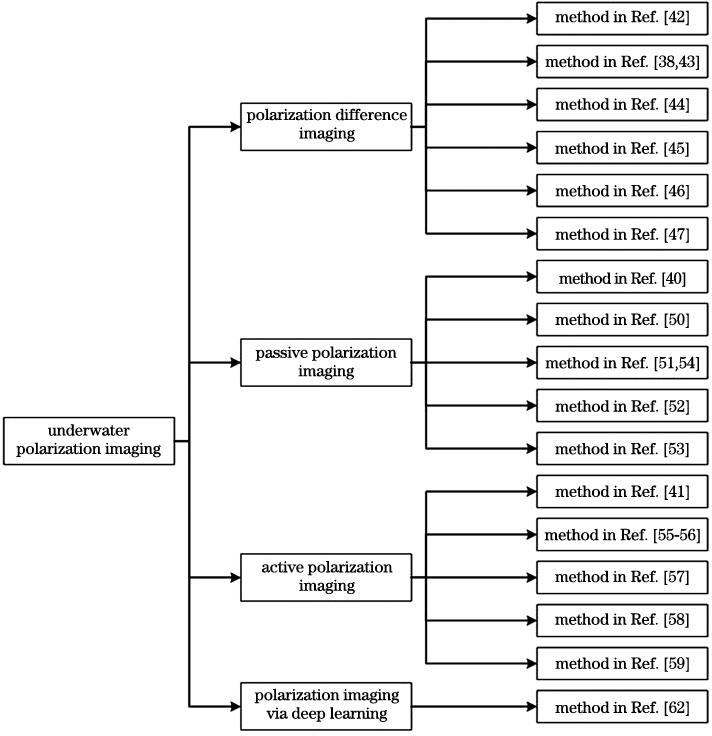
Fig. 1. Categories of underwater polarization imaging methods
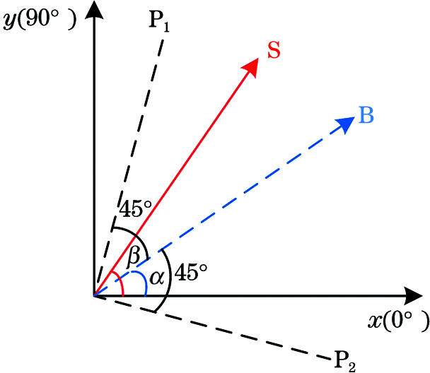
Fig. 2. Detection principle of polarization difference imaging
Fig. 3. Comparison of original intensity image and recovered image[42]. (a) Original intensity image; (b) recovered image
Fig. 4. Comparison of polarization-sum image's PSF and polarization-difference image's PSF[43]. (a) Polarization-sum image's PSF; (b) polarization-difference image's PSF
Fig. 5. Comparison of original intensity image and computational polarization-difference image based on the Stokes vector[46]. (a) Intensity image; (b) polarization-difference image; (c) normalized intensity curves
Fig. 6. Recovered results and evaluation curves[47]. (a) Curves of PCE, contrast, image sharpness, and image edge intensity; (b)--(d) recovered images of different image pairs
Fig. 7. Physical model of underwater passive polarization imaging[40]
Fig. 8. Comparison of recovered result of traditional underwater passive polarization imaging[40]
Fig. 9. Relationship between K(x,y) and ΔD(x,y)[50]
Fig. 10. Comparison between original intensity image and the recovered image by Huang's method[50]
Fig. 11. Schematic of transmittance correction[51]
Fig. 12. Comparison between original intensity images and the recovered images by different methods[51]
Fig. 13. Flowchart of passive underwater polarization imaging technology in neritic area[52]
Fig. 14. Recovered images of passive underwater polarization imaging technology in neritic area[53]. (a1) Original intensity image; (b1)--(d1) intensity distribution in the R, G, B channels of original intensity image; (a2) reconstructed image; (b2)--(d2) intensity distribution in the R, G, B channels of reconstructed image; (a3) intensity image in clear water; (b3)--(d3) intensity distribution in the R, G, B channels of intensity image in clear water; (a
Fig. 15. Recovered image of passive underwater polarization imaging technology in neritic area in real scene[53]. (a) Original intensity image; (b) recovered image
Fig. 16. Polynomial fitting of non-uniform scene area[54]. (a) Intensity fitting of backscattered light; (b) degree of polarization fitting of backscattered light
Fig. 17. Comparison of image restoration in non-uniform scene. (a) Recovered image by Hu's method[54]; (b) recovered image by Schechner's method[40]; (c) original intensity image
Fig. 18. Physical model of underwater active polarization imaging[41]
Fig. 19. Recovered image of traditional underwater active polarization imaging[41]. (a) Original intensity image; (b) picture of target information light; (c) picture of backscattered light
Fig. 20. Relationship between ESF, LSF, and PSF[55]
Fig. 21. Flowchart of removing forward scattered light in active underwater imaging[55]
Fig. 22. Restoration of badminton target[55]. (a) Original intensity image; (b) detail enlarged view of intensity image; (c) recovered image; (d) detail enlarged view of recovered image
Fig. 23. Comparison of Fourier spectra and intensity statistics values of intensity image and recovered image[55]. (a)(b) Original intensity image and its Fourier spectrum; (c)(d) recovered image and its Fourier spectrum; (e) intensity statistics value of the 240th row pixel of intensity image and recovered image
Fig. 24. Restoration results of different targets by multi-scale underwater polarization imaging[56]. The left part is original intensity image and the right part is the recovered image
Fig. 25. Diagram of imaging correlation solution[57]
Fig. 26. Recovered results in water with gradually varied turbidity[57]. (a1)--(f1) Using blue light illumination; (a2)--(f2) using Liu's method
Fig. 27. Comparison between original intensity images and the recovered images by Feng's method[58]. (a)(c)(e) Original intensity images; (b)(d)(f) recovered images
Fig. 28. Original intensity images and recovered images by Guan's method in turbid water with gradually varied depth[59]
Fig. 29. Architecture of polarimetric dense network[62]
Fig. 30. Comparison between recovered images by Polarimetric-Net and Intensity-Net[62]. (a)--(c) Original intensity image, recovered image by Polarimetric-Net, recovered image by Intensity-Net; (d)--(f) enlarged frame of selection area

Set citation alerts for the article
Please enter your email address
© Copyright 2018-2021 | Chinese Laser Press. All Rights Reserved 沪ICP备15018463号-20