
Xue-Mei Wen, Yan-Gang Bi, Fang-Shun Yi, Xu-Lin Zhang, Yue-Feng Liu, Wen-Quan Wang, Jing Feng, Hong-Bo Sun. Tunable surface plasmon-polariton resonance in organic light-emitting devices based on corrugated alloy electrodes[J]. Opto-Electronic Advances, 2021, 4(8): 200024-1
- Opto-Electronic Advances
- Vol. 4, Issue 8, 200024-1 (2021)
Abstract
Keywords
Introduction
Organic light-emitting devices (OLEDs), with the advantages of wide material selection, broadband spectra, high brightness, thin thickness, wide viewing angle, transparency and flexibility
The wavelength of excited SPP resonance can also be modified by material properties of the metal/dielectric interface
Material and method
Fabrication of periodic corrugations
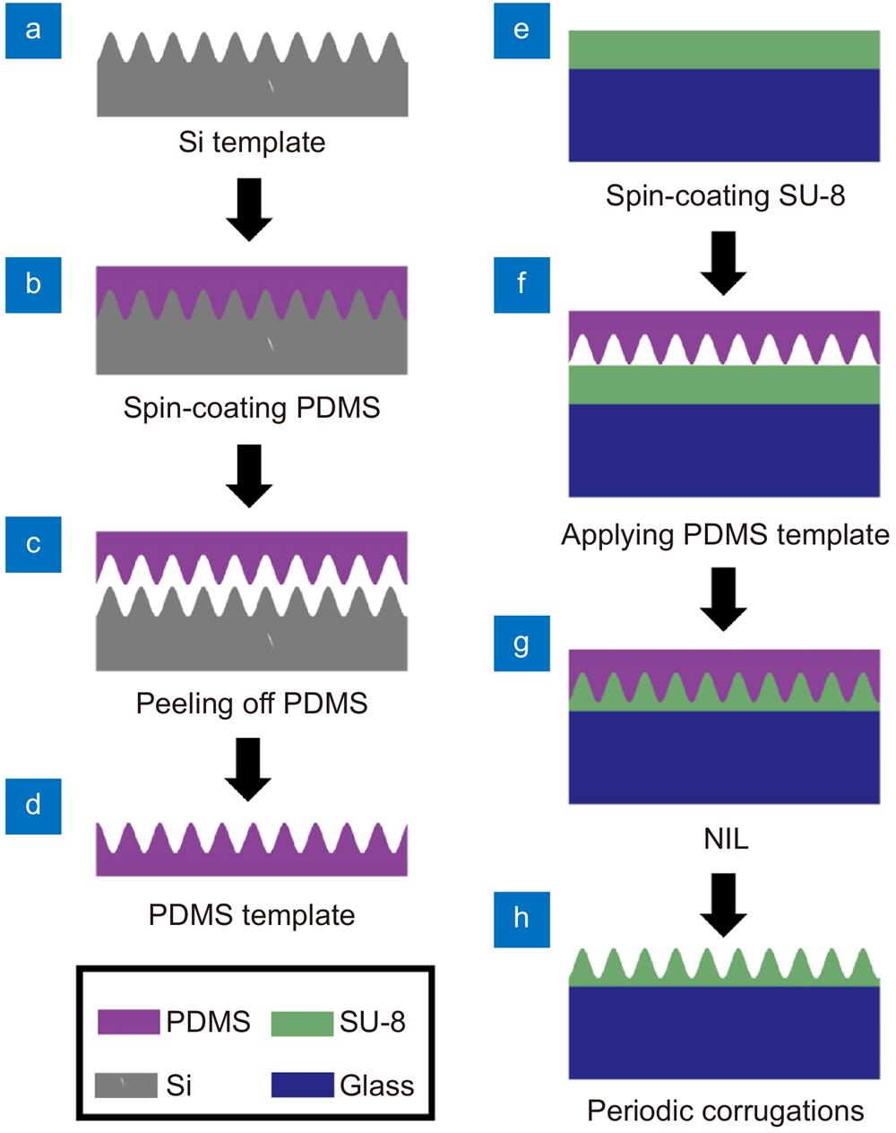
The fabrication process of the periodic corrugations based on NIL is described in Fig. 1. The Si template with 290 nm periodic corrugations was cleaned with acetone and ethanol for three times at 75 °C, and then was covered by polydimethylsiloxane (PDMS) as shown in Fig. 1(a) and 1(b). In order to remove bubbles between the Si template and the PDMS, the sample was placed in a vacuum chamber for 30 min. After the PDMS was thermally solidified and peeled off, the corrugated structures on the Si template were transferred to the PDMS film (Fig. 1(c) and 1(d)).
SU-8 2025 photoresist (MicroChem Corp.) was diluted with cyclopentanone to 0.1 g/mL, and then spin-coated on a precleaned glass substrate at 2000 rpm for 30 s (Fig. 1(e)). The substrate was dried in an oven at 95 °C for 30 min. The SU-8 coated glass substrate was covered by the prepared PDMS template with corrugations (Fig. 1(f)), and then placed in a chamber of the NIL system (CNI1-5vac, NIL Technology Company). After the NIL process for 20 min at 5 bar and 100 °C, the corrugations with period of 290 nm were transferred to the SU-8 film (Fig. 1(g) and 1(h)). Finally, the corrugated SU-8 was exposed under ultraviolet (UV) for 1 min to solidify.
![]()
Figure 1.
Fabrication of Ag-Al alloy electrodes and OLEDs
Ag-Al alloy electrodes and OLEDs were obtained by physical vapor deposition. The glass substrates covered by SU-8 film were placed in a vacuum chamber. 3 nm MoO3 and 8 nm Au were first deposited on the substrate as a transparent ultrathin metal anode, and MoO3 served as a seed layer to suppress the Volmer–Weber growth of Au
The absorption spectra of corrugated OLEDs was measured by a UV-Vis spectrophotometer (UV-2550, SHIMADZU), and a rotatable sample holder was fixed in the UV-Vis spectrophotometer to measure the angle-dependent absorption spectra. The electroluminescence (EL) performance of OLEDs were characterized by a Keithley 2400 Source Meter and PR-655 spectroradiometer (Photo Research Inc.). In order to detect the angle-dependent EL properties of OLEDs, the devices were fixed on a rotating stage and PR-655 spectroradiometer was set in the vertical direction.
Numerical simulation
The Finite-difference time-domain (FDTD) method was applied for numerical simulation. The metal and alloy electrodes were based on Drude model. The refractive indices of the organic materials in OLEDs were experimentally measured by ellipsometry. A modulated Gaussian pulse was applied as the incident light. Periodic boundary conditions and perfectly matched layers were set for the FDTD simulation.
Results and discussion
NIL process was used to transfer the corrugations with a period of 290 nm from a Si template to the SU-8 film on the substrate, with PDMS as the transfer medium. The surface morphology of the corrugated SU-8 film was characterized by AFM, and the periodic corrugation prepared by NIL has a uniform morphology with a precise period of 290 nm and a neat height of 55 nm (Fig. 2(a) and 2(b)). After the corrugation was prepared on the SU-8-coated substate, an ultrathin Au electrode and an OLED were thermally deposited. The surface morphologies of the periodic corrugations before and after the deposition of ultrathin Au film are compared in Fig. 2. The corrugations exhibit the fixed period and amplitude without obvious changes of the surface morphology. The AFM images and the height profiles demonstrate that the thermal deposition process cannot damage the corrugated SU-8 films, and the corrugations can be expected to copy and transfer to each functional layers of OLEDs during the subsequent deposition process.
![]()
Figure 2.The AFM images of corrugations (
To effectively improve the photons extraction of the OLEDs, the excited SPP resonance should match the light-emitting wavelength of OLEDs. The emission peak of Ir(BT)2(acac)-based OLEDs is located at 564 nm
![]()
Figure 3.(
Ag-Al alloy cathodes with different composition ratios can be easily obtained by changing the deposition rate of Ag and Al during the co-deposition process. We controlled the deposition rate of Ag at 0.16 nm/s, and the deposition rate of Al was adjusted to 0.008 nm/s, 0.016 nm/s, and 0.024 nm/s. As a result, the Ag: Al composition molar ratios of the alloy electrodes were about 0.952∶0.048, 0.909∶0.091, and 0.870∶0.130, respectively. The enhanced absorption spectra of corrugated OLEDs based on alloy cathodes with various composition ratios are shown in Fig. 4(a). As the Ag composition ratio decreases in the alloy, the enhanced absorption peak gradually blue-shifts from 583 nm, corresponding to the Ag-cathode-based OLEDs, to 518 nm associated with Al-cathode-based devices. The enhanced absorption peaks of OLEDs based on Ag0.952Al0.048, Ag0.909Al0.091, and Ag0.870Al0.130 alloy cathodes are 572 nm, 564 nm, and 555 nm, respectively, and the corrugated Ag0.909Al0.091 alloy electrode induced SPP resonant peak is in accordance with the light-emitting wavelength of Ir(BT)2(acac). To further confirm the enhanced absorption peaks arising from the excited SPP mode, the angle-dependent absorption spectra of Ag0.909Al0.091-based OLEDs were measured in Fig. 4(b). The absorption peak splits when the angle changes and the split peaks shift with angles, which is consistent with the characteristics of SPP resonant peak. It can be concluded that the corrugated Ag-Al alloy electrode, with composition molar ratio of 0.909 (Ag)∶ 0.091 (Al) and period of 290 nm, can effectively excite the SPP mode in OLEDs at the desired light-emitting wavelength of 564 nm.
![]()
Figure 4.(
The EL performances of OLEDs with corrugated Ag0.909Al0.091 alloy cathode are summarized in Fig. 5. Planar OLEDs with the same alloy electrodes are also compared. By introducing the plasmonic corrugations with period of 290 nm, the luminance and efficiency of OLEDs have been obviously improved. Luminance is enhanced from 74810 cd/m2 for planar OLEDs to 93320 cd/m2 for the corrugated devices, and current efficiency is improved from 32.63 cd/A to 39.46 cd/A, resulting in the enhancement of 25% in luminance and 21% in current efficiency, respectively. The corrugated OLEDs exhibits a higher current density than planar devices, and the corrugated device operated at 6 V demonstrates the higher brightness than the planar device from the photos in the inset of Fig. 5(a). OLEDs with and without corrugations have almost the same EL spectra as shown in Fig. 5(c). The angle-dependent EL spectra of the corrugated OLEDs were further measured under TM polarization. It can be clearly observed from Fig. 5(d) that the EL spectra changes significantly at various observation angles. The emission peak of 564 nm at 0° gradually widens, splits and shifts with the increase of angles, which is consistent with the angle-dependent absorption spectra in Fig. 4(b). From the above experimental results, we can confirm that the EL performance of OLEDs can be effectively increased by introducing periodic corrugations, and the improvements arise from the out-coupling of SPP mode which is excited at the desired light-emitting wavelength by the corrugated Ag-Al alloy electrode with an appropriate composition molar ratio.
![]()
Figure 5.
Conclusions
In summary, we design a corrugated Al-Ag alloy electrode with period of 290 nm in OLEDs based on nanoimprint lithography and co-deposition technologies to excite a tunable SPP mode. By modifying the deposition rates of Ag and Al to change the composition molar ratios of the alloy cathodes, a tunable SPP resonance in corrugated OLEDs has been realized without changing the period of the corrugations. The resonant wavelength of the excited SPP mode, induced by the corrugated Ag0.909Al0.091 alloy cathode in OLEDs, is exactly consistent with the emission peak of the OLEDs, and the photons trapped in SPP mode are effectively out-coupled and extracted. Due to the improved light extraction in OLEDs, the luminance and current efficiency of the OLEDs with corrugated Ag0.909Al0.091 alloy cathode have been increased by 25% and 21%, respectively.
References
[1] LH Liu, SL Li, L Wu, DF Chen, K Cao, et al. Enhanced flexibility and stability of PEDOT:PSS electrodes through interfacial crosslinking for flexible organic light-emitting diodes. Org Electron, 89, 106047(2021).
[2] Y Jeon, HR Choi, JH Kwon, S Choi, KM Nam, et al. Sandwich-structure transferable free-form OLEDs for wearable and disposable skin wound photomedicine. Light Sci Appl, 8, 114(2019).
[3] D Yin, ZY Chen, NR Jiang, YF Liu, YG Bi, et al. Highly transparent and flexible fabric-based organic light emitting devices for unnoticeable wearable displays. Org Electron, 76, 105494(2020).
[4] R Ding, FX Dong, MH An, XP Wang, MR Wang, et al. High-color-rendering and high-efficiency white organic light-emitting devices based on double-doped organic single crystals. Adv Funct Mater, 29, 1807606(2019).
[5] YG Huang, EL Hsiang, MY Deng, ST Wu. Mini-LED, Micro-LED and OLED displays: present status and future perspectives. Light Sci Appl, 9, 105(2020).
[6] MG Song, KS Kim, HI Yang, SK Kim, JH Kim, et al. Highly reliable and transparent Al doped Ag cathode fabricated using thermal evaporation for transparent OLED applications. Org Electron, 76, 105418(2020).
[7] D Yin, NR Jiang, YF Liu, XL Zhang, AW Li, et al. Mechanically robust stretchable organic optoelectronic devices built using a simple and universal stencil-pattern transferring technology. Light Sci Appl, 7, 35(2018).
[8] K Baek, DM Lee, YJ Lee, H Choi, J Seo, et al. Simultaneous emission of orthogonal handedness in circular polarization from a single luminophore. Light Sci Appl, 8, 120(2019).
[9] J Feng, YF Liu, YG Bi, HB Sun. Light manipulation in organic light-emitting devices by integrating micro/nano patterns. Laser Photonics Rev, 11, 1600145(2017).
[10] Y Qu, J Kim, C Coburn, SR Forrest. Efficient, nonintrusive outcoupling in organic light emitting devices using embedded microlens arrays. ACS Photonics, 5, 2453-2458(2018).
[11] A Salehi, XY Fu, DH Shin, F So. Recent advances in OLED optical design. Adv Funct Mater, 29, 1808803(2019).
[12] L Zhou, QD Ou, YQ Li, HY Xiang, LH Xu, et al. Efficiently releasing the trapped energy flow in white organic light-emitting diodes with multifunctional nanofunnel arrays. Adv Funct Mater, 25, 2660-2668(2015).
[13] J Choi, YS Shim, CH Park, H Hwang, JH Kwack, et al. Junction-free electrospun ag fiber electrodes for flexible organic light-emitting diodes. Small, 14, 1702567(2018).
[14] T Putnin, C Lertvachirapaiboon, R Ishikawa, K Shinbo, K Kato, et al. Enhanced organic solar cell performance: Multiple surface plasmon resonance and incorporation of silver nanodisks into a grating-structure electrode. Opto-Electron Adv, 2, 190010(2019).
[15] YG Bi, YF Liu, XL Zhang, D Yin, WQ Wang, et al. Ultrathin metal films as the transparent electrode in ITO-free organic optoelectronic devices. Adv Opt Mater, 7, 1800778(2019).
[16] M Morales-Masis, Wolf De, R Woods-Robinson, JW Ager, C Ballif. Transparent electrodes for efficient optoelectronics. Adv Electron Mater, 3, 1600529(2017).
[17] MD Ho, YY Liu, DS Dong, YM Zhao, WL Cheng. Fractal gold nanoframework for highly stretchable transparent strain-insensitive conductors. Nano Lett, 18, 3593-3599(2018).
[18] FS Yi, YG Bi, XL Zhang, D Yin, YF Liu, et al. Highly flexible and mechanically robust ultrathin Au grid as electrodes for flexible organic light-emitting devices. IEEE Trans Nanotechnol, 18, 776-780(2019).
[19] WL Barnes, A Dereux, TW Ebbesen. Surface plasmon subwavelength optics. Nature, 424, 824-830(2003).
[20] C Ma, XM Gao, YG Bi, FS Yi, XL Zhang, et al. Directly imprinted periodic corrugation on ultrathin metallic electrode for enhanced light extraction in organic light-emitting devices. IEEE Trans Nanotechnol, 18, 1057-1062(2019).
[21] YG Bi, J Feng, YS Liu, YF Li, Y Chen, et al. Surface plasmon-polariton mediated red emission from organic light-emitting devices based on metallic electrodes integrated with dual-periodic corrugation. Sci Rep, 4, 7108(2014).
[22] M Xu, J Feng, YS Liu, Y Jin, HY Wang, et al. Effective and tunable light trapping in bulk heterojunction organic solar cells by employing Au-Ag alloy nanoparticles. Appl Phys Lett, 105, 153303(2014).
[23] CY Huang, XP Zhang, JS Wang, CY Hong. Toward electrically pumped polymer lasing: light-emitting diodes based on microcavity arrays of distributed bragg gratings. Adv Opt Mater, 6, 1800806(2018).
[24] HW Liang, HC Hsu, JN Wu, XF He, MK Wei, et al. Corrugated organic light-emitting diodes to effectively extract internal modes. Opt Express, 27, A372-A384(2019).
[25] RF Garcia, L Zeng, S Khadir, M Chakaroun, APA Fischer, et al. Enhanced electroluminescence of an organic light-emitting diode by localized surface plasmon using Al periodic structure. J Opt Soc Am B, 33, 246-252(2016).
[26] NC Lindquist, WA Luhman, SH Oh, RJ Holmes. Plasmonic nanocavity arrays for enhanced efficiency in organic photovoltaic cells. Appl Phys Lett, 93, 123308(2008).
[27] LL Deng, JQ Yang, N Zhan, TY Yu, HT Yu, et al. High-performance solution-processed white organic light-emitting diodes based on silica-coated silver nanocubes. Opt Lett, 44, 983-986(2019).
[28] P Andrew, WL Barnes. Energy transfer across a metal film mediated by surface plasmon polaritons. Science, 306, 1002-1005(2004).
[29] YS Liu, S Guo, FS Yi, J Feng, HB Sun. Highly flexible organic-inorganic hybrid perovskite light-emitting devices based on an ultrathin Au electrode. Opt Lett, 43, 5524-5527(2018).
[30] YG Bi, J Feng, YF Li, Y Jin, YF Liu, et al. Enhanced efficiency of organic light-emitting devices with metallic electrodes by integrating periodically corrugated structure. Appl Phys Lett, 100, 053304(2012).


Set citation alerts for the article
Please enter your email address

© Copyright 2018-2021 | Chinese Laser Press. All Rights Reserved 沪ICP备15018463号-20