Natalie A. Mica1, Rui Bian2, Pavlos Manousiadis1, Lethy K. Jagadamma1, Iman Tavakkolnia2, Harald Haas2、3、*, Graham A. Turnbull1、4、*, and Ifor D. W. Samuel1、5、*
Author Affiliations
1Organic Semiconductor Centre, SUPA, School of Physics and Astronomy, St Andrews, Fife KY16 9SS, UK2LiFi Research and Development Centre, Institute for Digital Communications, School of Engineering, University of Edinburgh, Edinburgh EH9 3FD, UK3e-mail: H.Haas@ed.ac.uk4e-mail: gat@st-andrews.ac.uk5e-mail: idws@st-andrews.ac.ukshow less
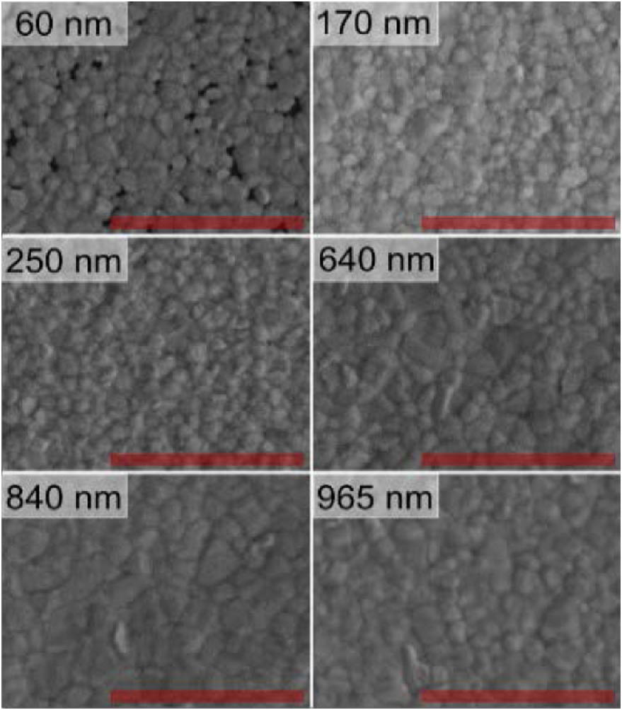
Fig. 1. SEM images of triple-cation perovskite films for all thicknesses. The red bar corresponds to a length of 2 μm.
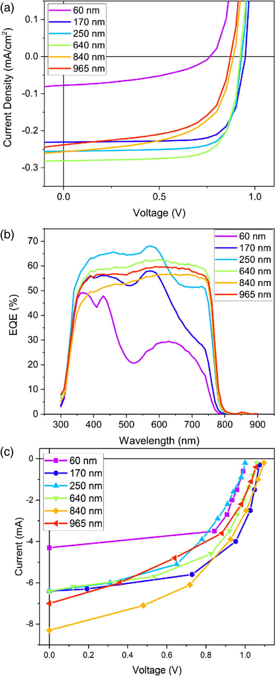
Fig. 2. Triple-cation perovskite devices with their (a) best J-V curves under 0.9 mW/cm2 indoor white LED illumination, (b) EQE, and (c) I-V curves under 50 mW red laser (660 nm) illumination.
Fig. 3. Low-magnification SEM images of the three thickest triple-cation perovskite films. The blue scale bar represents a length of 10 μm.
Fig. 4. (a) Box and whisker distributions of the −3 dB bandwidth and (b) achieved data rate for perovskite devices with varied active layer thickness. Here, the mean of the data is represented as a square, the median a solid line, and the ends of the box represent the 25%–75% range.
Fig. 5. (a) Transient photovoltage measurements for triple-cation perovskite solar cells with varied thickness. (b) Fitted RC time constant from this measurement.
Fig. 6. Example frequency response for each perovskite thickness device.
Fig. 7. Example of bit loading from one measurement of each thickness: (a) 60 nm, (b) 170 nm, (c) 250 nm, (d) 640 nm, (e) 840 nm, (f) 965 nm.
Perov. Thickness [nm] | Best PCE [%] | PCE [%] | FF [%] | [] | [V] | [] | [] | 60 | 2.9 | | | | | | | 170 | 18.7 | | | | | | | 250 | 20.3 | | | | | | | 640 | 21.4 | | | | | | | 840 | 14.9 | | | | | | | 965 | 13.8 | | | | | | |
|
Table 1. Cell Performance of Triple-Cation Devices with Varied Active Layer Thickness Using a White LED with an Incident Optical Power of a,b
Perov. Thickness [nm] | EQE under Low Intensity [%] | EQE with Red Laser [%] | PCE with Red Laser [%] | Power Generated [mW] | 60 | 28 | 16 | 6.1 | 3.1 | 170 | 39 | 24 | 9.0 | 4.5 | 250 | 53 | 24 | 6.5 | 3.3 | 640 | 61 | 24 | 7.7 | 3.9 | 840 | 56 | 31 | 8.8 | 4.4 | 965 | 59 | 26 | 6.7 | 3.3 |
|
Table 2. External Quantum Efficiency of Triple-Cation Solar Cells under 660 nm Low Intensity and Laser Illumination, and Power Conversion Efficiency and Power Generated under 50 mW Laser Power
Perov. Thickness [nm] | Bandwidth [kHz] | Data Rate [Mbps] | BER | Sample Size | 60 | | | | 10 | 170 | | | | 8 | 250 | | | | 13 | 640 | | | | 12 | 840 | | | | 14 | 965 | | | | 21 |
|
Table 3. Average and Standard Deviation of Bandwidth, Data Rate, BER, and Number of Measured Samples of Triple-Cation Photodetectors with Varied Active Layer Thickness
Perov. Thickness [nm] | | [ns] | | [ns] | 60 | 91.3 | 2.0 | 4.6 | 8.2 | 170 | 101.3 | 4.2 | 10.7 | 11.5 | 250 | 9.0 | 8.1 | 0.2 | 28.1 | 640 | 7.1 | 18.2 | 1.5 | 83.4 | 840 | 5.5 | 23.6 | 3.8 | 70.7 | 965 | 5.3 | 59.4 | 3.9 | 125.5 |
|
Table 4. Coefficients and Lifetimes Extracted from the Two-Exponential Fit of TRPL Data for All Perovskite Devices of Varied Active Layer Thicknessa
Perov. Thickness [nm] | Bandwidth Estimation | Transient Photovoltage | [ns] | Cell Resistance [] | Capacitance [nF] | Fitted RC Time Const. [ns] | Calculated [kHz] | 60 | 1485 | 271 | 5.5 | 1140 | 142 | 170 | 569 | 138 | 4.1 | 570 | 285 | 250 | 385 | 135 | 2.9 | 390 | 415 | 640 | 293 | 187 | 1.6 | 280 | 582 | 840 | 264 | 239 | 1.1 | 260 | 606 | 965 | 221 | 269 | 0.8 | 230 | 700 |
|
Table 5. Measured Device Resistance, Calculated Capacitance, and RC Time Constant for Triple-Cation Devices of Varied Active Layer Thickness Using Two Methods: Bandwidth Estimation and Transient Photovoltage
Perovskite Thickness [nm] | Precursor Solution Concentration [mol/L] | Spin-Coating Condition | 60 | 0.25 | 6000 r/min (40 s) | 170 | 0.25 | 1000 r/min (40 s) | 250 | 0.5 | 2000 r/min (30 s) | 640 | 1 | 2000 r/min (30 s) | 840 | 1 | 1400 r/min (40 s) | 965 | 1 | 1000 r/min (40 s) |
|
Table 6. Spin Coating Conditions for the Triple-Cation Perovskite Film Formationa