• High Power Laser Science and Engineering
  • Vol. 6, Issue 1, 01000e10 (2018)
Lei Ren1、2、†, Ping Shao1、2, Dongfeng Zhao1、2, Yang Zhou1、2, Zhijian Cai1、2, Neng Hua1、2, Zhaoyang Jiao1、2, Lan Xia1、3, Zhanfeng Qiao1、2, Rong Wu1、2, Lailin Ji1、3, Dong Liu1、3, Lingjie Ju1、2, Wei Pan1、2, Qiang Li1、2, Qiang Ye1、2, Mingying Sun1、2, Jianqiang Zhu1、2, and Zunqi Lin1、2
Author Affiliations
  • 1National Laboratory on High Power Laser and Physics, Shanghai Institute of Optics and Fine Mechanics, Chinese Academy of Sciences, Shanghai 201800, China
  • 2Key Laboratory of High Power Laser and Physics, Shanghai Institute of Optics and Fine Mechanics, Chinese Academy of Sciences, Shanghai 201800, China
  • 3Shanghai Institute of Laser Plasma, China Academy of Engineering Physics, Shanghai 201800, China
  • show less
    DOI: 10.1017/hpl.2018.4 Cite this Article Set citation alerts
    Lei Ren, Ping Shao, Dongfeng Zhao, Yang Zhou, Zhijian Cai, Neng Hua, Zhaoyang Jiao, Lan Xia, Zhanfeng Qiao, Rong Wu, Lailin Ji, Dong Liu, Lingjie Ju, Wei Pan, Qiang Li, Qiang Ye, Mingying Sun, Jianqiang Zhu, Zunqi Lin. Target alignment in the Shen-Guang II Upgrade laser facility[J]. High Power Laser Science and Engineering, 2018, 6(1): 01000e10 Copy Citation Text show less
    Target and beam alignment in a shooting experiment.
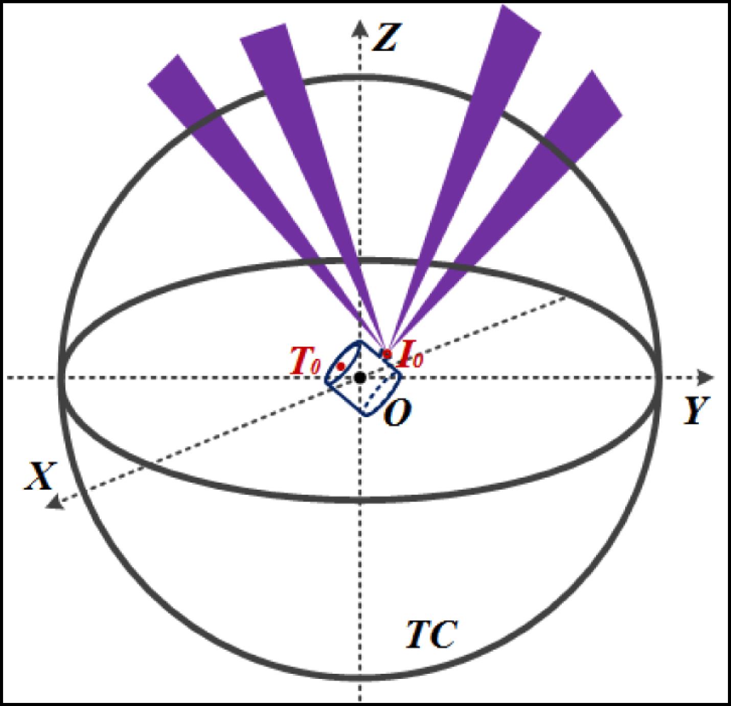
    Fig. 1. Target and beam alignment in a shooting experiment.
    Coordinate systems in aligning the target. The CCS is the fiducial for all the three systems.
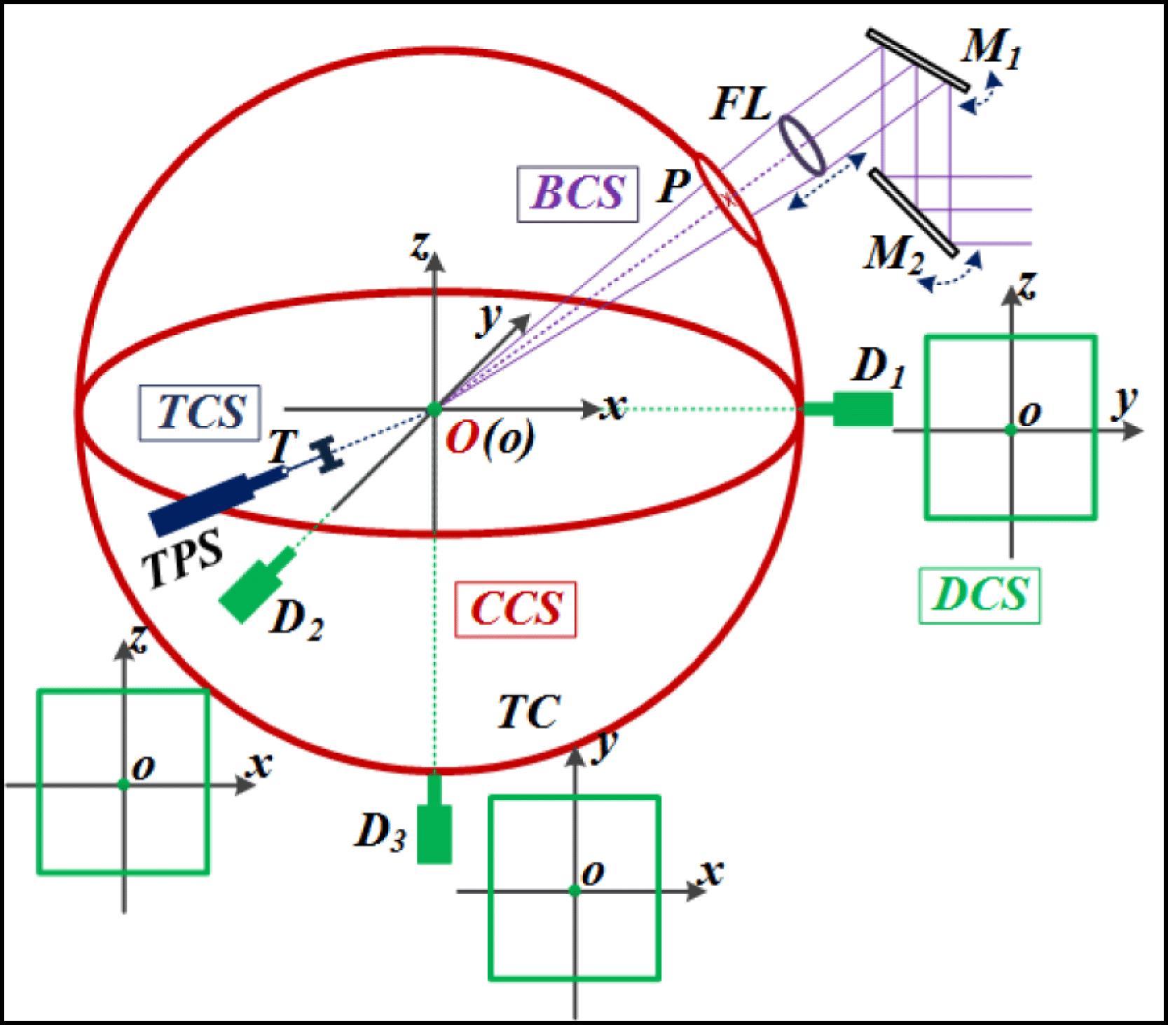
    Fig. 2. Coordinate systems in aligning the target. The CCS is the fiducial for all the three systems.
    Target area architecture of the SG-II-U facility.
    Fig. 3. Target area architecture of the SG-II-U facility.
    Top view of the distribution of the alignment units, the 8-beam nanosecond lasers, and the 9th beam PW laser in the target chamber. $U$ and $B$ represent the lasers shooting the target from the top and bottom part of the target chamber, respectively. $E$ denotes the equator plane of the target chamber.
    Fig. 4. Top view of the distribution of the alignment units, the 8-beam nanosecond lasers, and the 9th beam PW laser in the target chamber. $U$ and $B$ represent the lasers shooting the target from the top and bottom part of the target chamber, respectively. $E$ denotes the equator plane of the target chamber.
    Chamber center reference system. Mirror ($+$) denotes a mirror with a crosshair.
    Fig. 5. Chamber center reference system. Mirror ($+$) denotes a mirror with a crosshair.
    Target alignment sensor.
    Fig. 6. Target alignment sensor.
    SG-II-U beam path and the alignment beam unit. TSF and CSF are transport spatial filter and cavity spatial filter, respectively. PEPC donates the plasma electrode Pockels cell, which functions as a polarization switch.
    Fig. 7. SG-II-U beam path and the alignment beam unit. TSF and CSF are transport spatial filter and cavity spatial filter, respectively. PEPC donates the plasma electrode Pockels cell, which functions as a polarization switch.
    Target positioning system.
    Fig. 8. Target positioning system.
    Target preloading workbench.
    Fig. 9. Target preloading workbench.
    PW laser auxiliary alignment system.
    Fig. 10. PW laser auxiliary alignment system.
    Target alignment sequence.
    Fig. 11. Target alignment sequence.
    Target alignment images from a hohlraum in the TAS. The blue solid square denotes the real-time position, while the red dotted square indicates the alignment destination.
    Fig. 12. Target alignment images from a hohlraum in the TAS. The blue solid square denotes the real-time position, while the red dotted square indicates the alignment destination.
    Test configuration of the PW laser pointing error and the target used in the experiment.
    Fig. 13. Test configuration of the PW laser pointing error and the target used in the experiment.
    Offset of the PW beam centroid to the net crossings.
    Fig. 14. Offset of the PW beam centroid to the net crossings.
    Six-LEH hohlraums: sphere (left) and TACH (right).
    Fig. 15. Six-LEH hohlraums: sphere (left) and TACH (right).
    Geometrical rotation principle of the SdRS.
    Fig. 16. Geometrical rotation principle of the SdRS.
    Space-diagonal rotation sensor.
    Fig. 17. Space-diagonal rotation sensor.
    Three working conditions of the SdRS.
    Fig. 18. Three working conditions of the SdRS.
    ItemExplanationEvaluated
    $\unicode[STIX]{x1D703}_{\text{MLD}}$Main laser drift$5~\unicode[STIX]{x03BC}$rad
    $\unicode[STIX]{x1D703}_{\text{BR}}$Beam recognition in CCD$0.6~\unicode[STIX]{x03BC}$rad
    $\unicode[STIX]{x1D703}_{\text{CW}}$Alignment of CW laser$2~\unicode[STIX]{x03BC}$rad
    $\unicode[STIX]{x1D703}_{\text{Mirror}}$Mirror drift$0.68~\unicode[STIX]{x03BC}$rad
    $\unicode[STIX]{x1D703}_{\text{FOA}}$FOA drift$1~\unicode[STIX]{x03BC}$rad
    $\unicode[STIX]{x1D703}_{\text{HVAC}}$Internal HVAC transient$0.1~\unicode[STIX]{x03BC}$rad
    $\unicode[STIX]{x1D6E5}_{\text{TP}}$Target positioning$8~\unicode[STIX]{x03BC}$m
    $\unicode[STIX]{x1D6E5}_{\text{TR}}$Target recognition in CCD$8~\unicode[STIX]{x03BC}$m
    Total$20.6~\unicode[STIX]{x03BC}$m
    Table 1. Alignment error budget in the nanosecond laser system.
    Lei Ren, Ping Shao, Dongfeng Zhao, Yang Zhou, Zhijian Cai, Neng Hua, Zhaoyang Jiao, Lan Xia, Zhanfeng Qiao, Rong Wu, Lailin Ji, Dong Liu, Lingjie Ju, Wei Pan, Qiang Li, Qiang Ye, Mingying Sun, Jianqiang Zhu, Zunqi Lin. Target alignment in the Shen-Guang II Upgrade laser facility[J]. High Power Laser Science and Engineering, 2018, 6(1): 01000e10
    Download Citation