1National Laboratory on High Power Laser and Physics, Shanghai Institute of Optics and Fine Mechanics, Chinese Academy of Sciences, Shanghai 201800, China
2Key Laboratory of High Power Laser and Physics, Shanghai Institute of Optics and Fine Mechanics, Chinese Academy of Sciences, Shanghai 201800, China
3Shanghai Institute of Laser Plasma, China Academy of Engineering Physics, Shanghai 201800, China
Lei Ren, Ping Shao, Dongfeng Zhao, Yang Zhou, Zhijian Cai, Neng Hua, Zhaoyang Jiao, Lan Xia, Zhanfeng Qiao, Rong Wu, Lailin Ji, Dong Liu, Lingjie Ju, Wei Pan, Qiang Li, Qiang Ye, Mingying Sun, Jianqiang Zhu, Zunqi Lin. Target alignment in the Shen-Guang II Upgrade laser facility[J]. High Power Laser Science and Engineering, 2018, 6(1): 01000e10
Copy Citation Text
The Shen-Guang II Upgrade (SG-II-U) laser facility consists of eight high-power nanosecond laser beams and one short-pulse picosecond petawatt laser. It is designed for the study of inertial confinement fusion (ICF), especially for conducting fast ignition (FI) research in China and other basic science experiments. To perform FI successfully with hohlraum targets containing a golden cone, the long-pulse beam and cylindrical hohlraum as well as the short-pulse beam and cone target alignment must satisfy tight specifications (30 and $20~\unicode[STIX]{x03BC}\text{m}$ rms for each case). To explore new ICF ignition targets with six laser entrance holes (LEHs), a rotation sensor was adapted to meet the requirements of a three-dimensional target and correct beam alignment. In this paper, the strategy for aligning the nanosecond beam based on target alignment sensor (TAS) is introduced and improved to meet requirements of the picosecond lasers and the new six LEHs hohlraum targets in the SG-II-U facility. The expected performance of the alignment system is presented, and the alignment error is also discussed.
The Shen-Guang series of laser facilities were constructed to generate fusion ignition and gain in the laboratory[1–4]. The Shen-Guang II Upgrade (SG-II-U) facility consists of eight beams (in total 24 kJ/3 ns@3$\unicode[STIX]{x1D714}$) for implosion compression, and a petawatt (PW) beamline (1 kJ/1 ps@$\unicode[STIX]{x1D714}$)[5] for generating a relativistic electron beam. The facility is focused on the investigation of high energy density physics and inertial confinement fusion (ICF)[6], especially fast ignition (FI)[7–9] research in China. FI experiments have also been performed in many laser facilities, such as the OMEGA EP facility at the University of Rochester, the FIREX-I at Osaka University, the LMJ-Petal facility in France, and the Vulcan facility in the United Kingdom. Simultaneous alignment of the nanosecond and picosecond lasers and the targets is a challenge facing all these FI facilities.
Over the 30-year development of the SG series of laser facilities, research on target alignment was conducted at the National Laboratory on High Power Laser and Physics (NLHPLP), and some basic ideas and technology arising from this research were successfully used in the SG-II-U FI studies. During the construction of the SG-I target area, the idea of fiducial transmitting among different reference systems was utilized to detect the target position, and conduct beam pointing and focusing[10]. In the SG-II target area[11], to monitor the position of the shooting laser with different wavelengths ($\unicode[STIX]{x1D714}$, $2\unicode[STIX]{x1D714}$, $3\unicode[STIX]{x1D714}$, and $4\unicode[STIX]{x1D714}$), a long-focus reflection-type microtelescope with angular resolution was designed[12]. In combination with a Schmidt–Cassegrain telescope and an auto-collimation system, this microtelescope could be used for both position and angular deviation observation. This episcopic imaging system was also adapted for the alignment of the short-pulse picosecond PW laser (9th beam PW laser) in the SG-II-U facility.
Over the past 3 years, work has shown that a spherical hohlraum with six laser entrance holes (LEHs)[13, 14] or a three-axis cylindrical hohlraum (TACH)[15], which contains three orthogonally joined cylindrical hohlraums and six LEHs – with high symmetry on a capsule, and low possibility of plasma jet generation – seems superior to a cylindrical target. With more LEHs to be positioned and the shooting laser from six directions to be aligned, this target poses new challenges for alignment.
Sign up for High Power Laser Science and Engineering TOC. Get the latest issue of High Power Laser Science and Engineering delivered right to you!Sign up now
In this paper, the target and beam alignment in the SG-II-U facility is presented to meet the requirements of different types of targets and shooting methods. In Section 2, the basic principle and requirements of target alignment, and the procedure of the shooting target are introduced. In Section 3, the devices designed for different target alignments, such as cylindrical hohlraums with or without a golden cone, and both the long- and short-pulse laser beams, are presented. The hohlraum with six LEHs is discussed in Section 4. The target sensor was adapted to make it rotatable and thus, realize beam alignment for this kind of target. In Section 5, conclusions of the work are given and required future work is also discussed, which will increase the automatic nature, flexibility and efficiency of target alignment in the SG-II-U facility.
2 Basic principle of target alignment
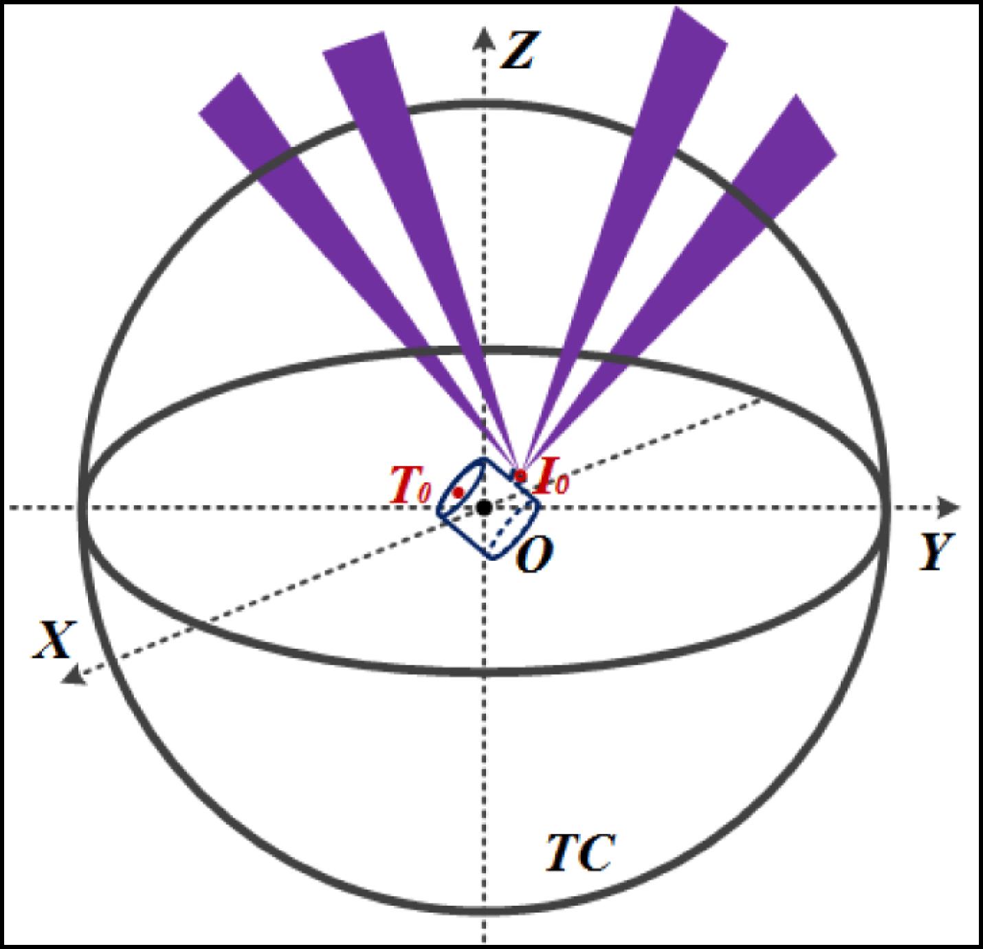
In one laser shooting experiment, a character point on the target had to be positioned somewhere in the target chamber (TC) $T_{0}$, as shown in Figure 1, and the beams had to be focused onto the position $I_{0}$ in the target. Since the chamber coordinates system (CCS) is a virtual system, only the coordinates of the target and the beam foci are known. However, it is necessary to see the real position within the system. Thus, when aligning the target, a real reference system, i.e., the detector coordinates system (DCS), was introduced to monitor the beam and target performance. In this way, the coordinates of the target and beam foci were transferred from the CCS (as O-XYZ), to the DCS, (as o-xyz). The DCS consisted of three orthogonal imaging systems, shown as $D_{1}$, $D_{2}$ and $D_{3}$ in Figure 2. Before the coordinates transformation, the fiducial of the CCS had to be rigorously transmitted to the DCS. The target chamber center (TCC) was usually set to be the fiducial to make the alignment of the physics diagnostic instruments convenient.
The experimental target was inserted into the chamber with the target positioning system (TPS), which also had its own target coordinate system (TCS). The fiducial of the CCS was transmitted to the TCS through alignment of the target moving axis, TO, with the TCC. The pointing and focusing of the shooting laser beam were described in the beam coordinate system (BCS), and were adjusted by translating the focusing lens (FL) along its optical axis and deflecting two of the guiding mirrors ($M_{1}$ and $M_{2}$ in Figure 2) in the switchyard of the target area[16]. When installing the FL, it was ensured that the optical axis was coincident with the connection of the beam port center ($P$ in Figure 2) on the TC and the TCC. In this way, the BCS was coupled with the CCS. When the BCS, TCS and DCS were all coupled with the CCS, the beam and target alignment could be performed in one reference system, the DCS. Although various alignment devices and procedures have been reported in the different laser fusion facilities, such as the NIF[17–19], LIL[20], LMJ[21, 22] and SG-II[11], the principle of the target alignment in these facilities is similar to that described in this work. In the SG-II-U facility, the target alignment system was flexible and the baseline cylindrical hohlraums, the primary and backlighter targets, and the hohlraums with a golden cone could be aligned. The shooting lasers from the vertical direction, from the horizontal direction as a backlight or a heating beam for FI, and even from the three orthogonal directions could also be aligned.
3 Target and beam alignment in the SG-II-U facility
The target area architecture of the SG-II-U facility is presented in Figure 3. Eight-beam nanosecond lasers, with an aperture of $310~\text{mm}^{2}$, were reflected and directed by four guiding mirrors in the switchyard, passed through the final optics assembly (FOA), and were focused on the target from the top and bottom hemisphere of the TC. After expansion and compression in the grating vessel, the $\unicode[STIX]{x1D6F7}$320 mm 9th beam PW laser was injected into the TC from the beam port at the eastside of the equator, deviating by a distance of 300 mm in the north direction, as shown in Figure 4. Subsequently, the PW laser was focused by an off-axis parabola mirror (OAPM), with a focal length of 800 mm, into the TCC. The beam and target alignment unit was composed of the following systems: the chamber center reference system (CCRS) and additional telescopes (ATs), the target alignment sensor (TAS), the TPS, the PW laser auxiliary alignment system (AAS), as shown in Figure 4 and the alignment beam unit. The TC was a vacuum sphere with a diameter of 2.4 m, and there was a total of 94 ports distributed on it serving different purposes, such as acting as a laser entrance, in physics diagnostics and target alignment, and so on.
3.1 Chamber center reference system
The CCRS was composed of two orthogonal long focal length reflection-type microtelescopes, which were distributed at the equatorial plane, in the northwest (CCRS-NW) and northeast (CCRS-NE) orientation of the TC. The microtelescopes contained a Schmidt–Cassegrain telescope, a 1:1 image relay system and an illumination system for auto-collimation, as shown in Figure 5. By changing the focal length of the telescope, the camera behind the beam splitter could be used for monitoring both the target and the auto-collimation system. The two optical imaging telescopes reconstructed the CCS and provided the fiducial for the target and beam alignment.
Apart from the two CCRS imaging systems, when necessary, three ATs could be installed in two poles, westside of the equator of the target chamber. These five optical systems made up the entire CCS, which could be used to align an abnormal target and beam from different shooting directions.
When aligning the normal cylindrical hohlraums in the indirect-drive ICF[23], two CCRS imaging systems were enough to satisfy the alignment requirements for the rotation symmetry characteristics of the target. The lasers shot from the top and bottom part of the target chamber to the target. Since the target could not be irradiated directly by the laser during the alignment before the formal shooting experiment, a TAS was used to detect the pointing and focusing of the shooting beams.
3.2 Target alignment sensor
The TAS was distributed at the equatorial plane, in the southeast orientation of the TC. It was inserted into the target chamber by the TAS positioner. After reaching the position near the TCC, it was aligned by the CCRS-NE/NW telescopes. Two orthogonal mirrors (W-Mirror and E-Mirror) with crosshairs were installed in the TAS, facing the northwest and northeast CCRS microtelescopes, separately. Two CCRS microtelescopes were first focused on the crosshair in the W/E-Mirror to calibrate the position of the TAS. Subsequently, the illumination source in the auto-collimation section of the CCRS was opened. The reticule was imaged through the 1:1 relay system and the Cassegrain telescope, and was also reflected by the W/E-Mirrors of the TAS to the camera. By adjusting the focal length of the Cassegrain telescope for a second time, the reticule was clearly imaged by the camera. In this manner, the attitude of the TAS was adjusted. Subsequently, the TAS was aligned to the TCC, and thus, could function as a DCS to align the hohlraum and the shooting lasers.
The TAS consisted mainly of three Lens-CCD units (A, B, C), two reflecting mirrors (an upper and lower mirror) and two mirrors with crosshairs (W/E-mirror ($+$)), as shown in Figure 6. The W/E-mirrors were designed for aligning the TAS itself using the CCRS. Lenses A, B and C were used to monitor the target position and attitude, while the reflecting mirrors were utilized for beam alignment. After reflection, the laser beams were focused into the A- and B-CCD units, where the top and bottom part of the target was also imaged through lenses A and B. In this way, the target and beam alignment shared the same fiducial and could be performed in parallel with only one device.
3.3 Alignment beam unit
The alignment beam unit provides the $3\unicode[STIX]{x1D714}$ surrogate beam for nanosecond beam alignment to the target. A 351 nm CW laser was inserted into the SG-II-U beam path near the transport spatial filter (TSF), as shown in Figure 7. The surrogate beam was focused to the target center with TAS and then a rod shot was fired to a target also positioned in the target center. Compare the pulsed beam centroids with the target center and the pointing of the alignment beam was adjusted according to the offset. Then, another rod shot was fired. In this manner, the alignment beam and the main laser beam will share the same beam path.
3.4 Target positioning system
The TPS was distributed at the equatorial plane, in the southwest orientation of the TC, perpendicular to the TAS positioner. During a shooting experiment, the target was loaded on the target holder, which was mounted in the 6-axes adjustment arm on the target loading port, as shown in Figure 8. Subsequently, the two-stage inserting linear slider transported the arm into the target chamber through the vacuum valves. All these components of the TPS were sealed in an auxiliary vessel, which made it possible to change the target without breaking the TC vacuum.
Before the target holder was mounted in the 6-axes adjustment arm, the attitude of the target in the holder was pre-adjusted in the target preloading workbench, as shown in Figure 9. This workbench incorporated two telescope views, representing the CCRS views that were positioned with respect to the target. By observing the image of the target in these two views monitored on the off-line screen, the attitude of the target was adjusted in the target holder and a more effective condition for target alignment in the chamber was realized.
3.5 PW laser auxiliary alignment system
The PW laser AAS is a large aperture telescope made of an achromatic lens and an off-axis parabola mirror (OAPM), as shown in Figure 10. In the FI experimental shot, there was a golden cone in the middle section of the cylindrical hohlraum target and the orientation of the cone was in the same direction as the PW laser, perpendicular to the hohlraum nanosecond LEHs. The telescope monitored both the focus of the PW laser and the center of the golden cone. During the alignment, a moveable standard plate with a parallelism of 0.4” was inserted into the PW laser path. While in the experimental shot, the plate was extracted from the path.
3.6 Alignment sequence
During the alignment of the target and beam for the FI experiment, all the systems discussed had to cooperate and their sequence of operation is shown in Figure 11.
Item
Explanation
Evaluated
$\unicode[STIX]{x1D703}_{\text{MLD}}$
Main laser drift
$5~\unicode[STIX]{x03BC}$rad
$\unicode[STIX]{x1D703}_{\text{BR}}$
Beam recognition in CCD
$0.6~\unicode[STIX]{x03BC}$rad
$\unicode[STIX]{x1D703}_{\text{CW}}$
Alignment of CW laser
$2~\unicode[STIX]{x03BC}$rad
$\unicode[STIX]{x1D703}_{\text{Mirror}}$
Mirror drift
$0.68~\unicode[STIX]{x03BC}$rad
$\unicode[STIX]{x1D703}_{\text{FOA}}$
FOA drift
$1~\unicode[STIX]{x03BC}$rad
$\unicode[STIX]{x1D703}_{\text{HVAC}}$
Internal HVAC transient
$0.1~\unicode[STIX]{x03BC}$rad
$\unicode[STIX]{x1D6E5}_{\text{TP}}$
Target positioning
$8~\unicode[STIX]{x03BC}$m
$\unicode[STIX]{x1D6E5}_{\text{TR}}$
Target recognition in CCD
$8~\unicode[STIX]{x03BC}$m
Total
$20.6~\unicode[STIX]{x03BC}$m
Table 1. Alignment error budget in the nanosecond laser system.
A surrogate sphere target was inserted into the TC with the TPS to provide the fiducial for the PW laser alignment and cone orientation. This sphere was aligned to the TCC with the CCRS.
The moveable plate in the AAS was inserted into the PW laser path to perform the PW laser alignment. The sphere centroid was updated in the AAS camera and its position at the TCC was recorded. The seed laser was shot from the PW laser frontend directly to the sphere to realize the pointing and focusing of the PW laser. The laser had a repetition rate of 1 Hz and was unamplified[24].
The sphere target was extracted and inserted into the TAS. The TAS was aligned with the CCRS so that the TCC was transferred to the TAS center.
The sphere target was exchanged with a cone hohlraum and the hohlraum was inserted into the TC. The images taken by the A, B and C-CCD units of the TAS (Figure 12)[25, 26] were combined and the camera of the AAS was used to carefully adjusted the cone hohlraum to make sure that both the hohlraum and the cone were in the right position and attitude. Parallelly, the alignment beam unit was inserted into the main laser beam path and the nanosecond lasers can be also aligned with the 3$\unicode[STIX]{x1D714}$ surrogate beam and TAS.
After the cone hohlraum and all the beams were aligned, the TAS and moveable plate were extracted, and the laser shoot occurred.
3.7 Alignment performance
The alignment error budget for nanosecond laser system is listed in Table 1, and the total alignment error can be calculated with Equation (1). In the SG-II-U facility, there are four guiding mirrors in the target area and the focus length of lens in the FOA is 2200 mm. The alignment error is $20.6~\unicode[STIX]{x03BC}\text{m}$ rms and this result can meet the requirement of nanosecond shooting experiment. $$\begin{eqnarray}\displaystyle \unicode[STIX]{x1D6E5}^{2} & = & \displaystyle (\unicode[STIX]{x1D703}_{\text{MLD}}\cdot f)^{2}+(\unicode[STIX]{x1D703}_{\text{BR}}\cdot f)^{2}+(\unicode[STIX]{x1D703}_{\text{CW}}\cdot f)^{2}\nonumber\\ \displaystyle & & \displaystyle +\,4\cdot \left(\mathop{\sum }_{i}\unicode[STIX]{x1D703}_{\text{Mirror}}\cdot f\right)^{2}+(\unicode[STIX]{x1D703}_{\text{FOA}}\cdot f)^{2}\nonumber\\ \displaystyle & & \displaystyle +\,(\unicode[STIX]{x1D703}_{\text{HVAC}}\cdot f)^{2}+\unicode[STIX]{x1D6E5}_{\text{TP}}^{2}+\unicode[STIX]{x1D6E5}_{\text{TR}}^{2}.\end{eqnarray}$$
As for the PW laser system, an Al coated planar target with $75~\unicode[STIX]{x03BC}\text{m}$ grid width was used in testing the PW laser pointing error, the optical path was shown in Figure 13. Seven rod shots were fired and the offset of the PW beam centroids to the net crossings was recorded in Figure 14. And the total pointing error was $9.76~\unicode[STIX]{x03BC}\text{m}$ rms, less than $10~\unicode[STIX]{x03BC}\text{m}$ rms.
In the PW beam path of the SG-II-U facility, there are four gratings, five mirrors and an OAPM in the target area, they can all be considered as guiding mirrors. The focus length of OAPM is 800 mm, and there is no FOA in the beam path. According to the Equation (1), the total alignment error for PW laser will be $17.62~\unicode[STIX]{x03BC}\text{m}$ rms, which can surely meet the requirement of $20~\unicode[STIX]{x03BC}\text{m}$ rms for the FI experiment.
The SG-II-U laser facility was completed in late 2015 and has been in operation ever since. Several rounds of FI experiments have been performed and the target alignment system has functioned well with errors less than $30~\unicode[STIX]{x03BC}\text{m}$ rms for the nanosecond alignment, $10~\unicode[STIX]{x03BC}\text{m}$ rms for the PW laser pointing, and $20~\unicode[STIX]{x03BC}\text{m}$ rms for the FI experiment. All the alignment was executed in a half-automatic mode. The automatic alignment control system is still under construction. The auto-alignment of standard form targets and nanosecond lasers has been realized; however, the alignment of the FI cone hohlraum and the PW laser is still performed manually and takes about 1 h with two people working together.
4 Alignment of the six-LEH hohlraums
In the past 3 years, work has shown that a hohlraum with three pairs of orthogonal LEHs, such as the spherical hohlraum with six LEHs and a TACH, leads to high symmetry on a capsule and the low possibility of plasma jet generation. This kind of hohlraum appears to be superior to a cylindrical target in indirect-drive ICF. With LEHs and shooting lasers from six directions to be aligned, these hohlraums also pose new challenges in the alignment of the beam and target.
4.1 Space-diagonal rotation sensor
Six-LEH hohlraums[13–15], as shown in Figure 15, have one more rotational degree of freedom and two more laser entrance directions compared to cylindrical targets. It is very difficult to align such a hohlraum with the TAS, which is designed for use with a cylindrical hohlraum.
Considering the rotation symmetry characteristics of the six LEHs, the spherical target, as an example (the same can be done with the TACH), can be changed into a cubic structure with its edge length the same as its diameter. Thus, the centers of the six LEHs coincide with the face centers, $H_{1}-H_{6}$, as shown in Figure 16. The orthogonal three LEHs, $H_{1}$, $H_{3}$ and $H_{5}$ were connected to form an equilateral triangle, $\unicode[STIX]{x1D6E5}H_{1}H_{3}H_{5}$ and a space diagonal $C_{1}C_{2}$, which was perpendicular to $\unicode[STIX]{x1D6E5}H_{1}H_{3}H_{5}$ and the interaction point $R$ was also at the center of $\unicode[STIX]{x1D6E5}H_{1}H_{3}H_{5}$. Alignment of the cubic structure with the TAS (represented by lenses A and B) was attempted, but it was rotatable. According to Figure 16, if the TAS lens line $H_{1}H_{2}$ is rotated by $120^{\circ }$ in the clockwise direction around the cubic center $O$ and along the space diagonal $C_{1}C_{2}$, it is clear that $H_{1}H_{2}$ will coincide with $H_{3}H_{4}$. Based on these geometrical relations, a space-diagonal rotation sensor (SdRS) was specially adapted from the TAS to align the 6-LEH hohlraums. This sensor was a combination of the TAS, a positioner, and rotation stages, as shown in Figure 17. The rotation axis of the stages must rigidly coincide with the space diagonal of the cubic unit, which virtually exists at the center of the SdRS.
4.2 Beam and target alignment
There were three working conditions of the SdRS, facing the three orthogonal shooting directions ($X$, $Y$, and $Z$) of the target, respectively. SdRS was originally at $0^{\circ }$, like the TAS, with which the lasers could be aligned in the $Z$ direction. By rotating the SdRS accurately by $120^{\circ }$, the lasers could be aligned in the $X$ direction, as shown in Figure 18. By rotating it again by $120^{\circ }$ to place it at $-120^{\circ }$, the lasers could be aligned in the $Y$ direction. After beam alignment, the SdRS returned to its original condition, where the hohlraum was inserted and aligned.
5 Conclusion
Target alignment is the last but crucial step before shooting a laser to perform a drive experiment. In this paper, the basic principle of target alignment, and the alignment units and procedure in the SG-II-U laser facility were discussed. Combined with CCRS, TAS and PW laser AAS, the facility performed an FI shooting experiment with an error of less than $20~\unicode[STIX]{x03BC}\text{m}$ rms. A specially designed device, SdRS, was used to address the 3D alignment difficulties in six-LEH hohlraums. Since the SG-II-U laser facility is newly built, there is still plenty of work to be done in automating the target alignment and in system control to improve the shooting efficiency. Experimental verification and error analysis of the use of SdRS in aligning the six-LEH hohlraums are also in progress.
References
[1] X. T. He. J. Phys.: Conf. Ser., 688(2016).
[2] Y. Gao, W. Ma, B. Zhu, Z. Cao, J. Zhu, X. Yang, Y. Dai, Z. Lin. 26th IEEE Photonics Conference (IPC), 73(2013).
[20] M. Mangeant, C. J. Hooker, J.-L. Dubois, R. André, M. Stupka, P. Dupont, V. Moreau, C. Lissayou, C. Lanternier, E. Bar, S. Devaure, A. Perrin, P. Auliac, Y. Schiano. Conference on Adaptive Optics for Laser Systems and Other Applications(2007).
[22] M. Geitzholz, P. Jeanpierre, C. Lanternier, A. Reichart. Third International Conference on Inertial Fusion Sciences and Applications (IFSA 2003), 584(2003).
[24] C. Wang, H. Wei, J. Wang, D. Huang, W. Fan, X. Li. Chin. Opt. Lett., 15(2017).
[25] X. Li, W. Song, Y. Zhang, X. Liu. Asia Simulation Conference/International Conference on System Simulation and Scientific Computing (AsiaSim and ICSC 2012), 73(2012).
Lei Ren, Ping Shao, Dongfeng Zhao, Yang Zhou, Zhijian Cai, Neng Hua, Zhaoyang Jiao, Lan Xia, Zhanfeng Qiao, Rong Wu, Lailin Ji, Dong Liu, Lingjie Ju, Wei Pan, Qiang Li, Qiang Ye, Mingying Sun, Jianqiang Zhu, Zunqi Lin. Target alignment in the Shen-Guang II Upgrade laser facility[J]. High Power Laser Science and Engineering, 2018, 6(1): 01000e10