• Infrared and Laser Engineering
  • Vol. 49, Issue 7, 20190519 (2020)
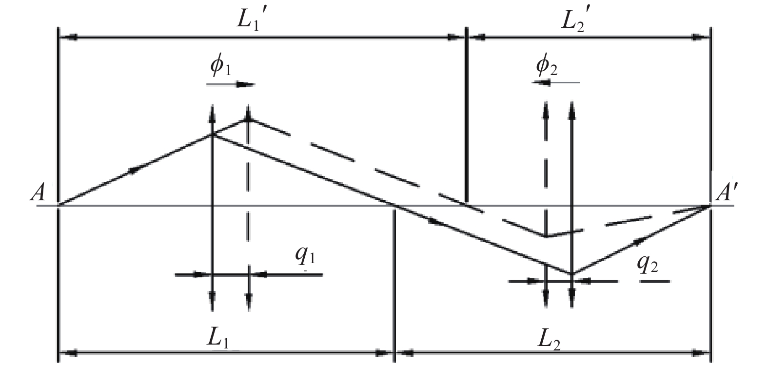
Conjugate distance graph of Φ1 and Φ2 groups
Fig. 1. Conjugate distance graph of Φ1 and Φ2 groups
Circle radius diagram of field of view. Radius of the image plane is 12.303 mm, aspect ratio of the image plane is 4:3, length of the long side is 13.648 9 mm, and length of the wide side is 10.236 7 mm
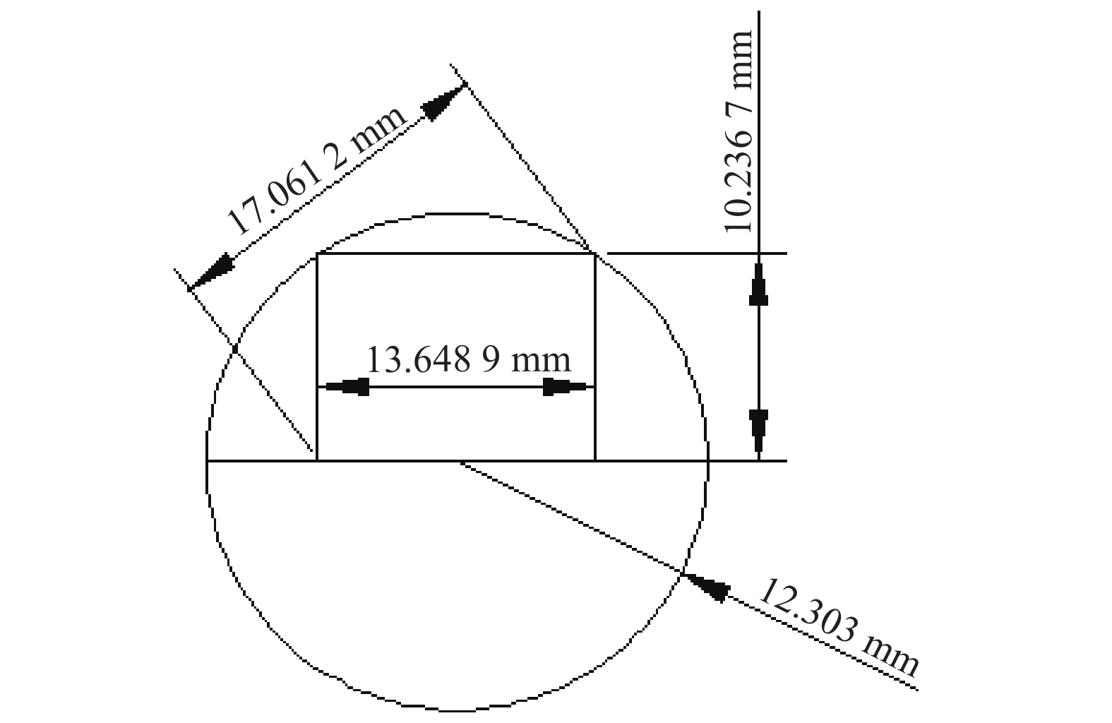
Fig. 2. Circle radius diagram of field of view. Radius of the image plane is 12.303 mm, aspect ratio of the image plane is 4:3, length of the long side is 13.648 9 mm, and length of the wide side is 10.236 7 mm
Optical scheme of a principle ray passing the negative meniscus lens
Fig. 3. Optical scheme of a principle ray passing the negative meniscus lens
Structural schematic of former-group lenses
Fig. 4. Structural schematic of former-group lenses
Structural schematic of rear-group lenses. the eleventh and thirteenth lenses are independent spherical lenses. The last plane is the image plane
Fig. 5. Structural schematic of rear-group lenses. the eleventh and thirteenth lenses are independent spherical lenses. The last plane is the image plane
Zoom-group planning. The first group is the front zoom group, the second group is the rear zoom group, and the last plane is the image plane
Fig. 6. Zoom-group planning. The first group is the front zoom group, the second group is the rear zoom group, and the last plane is the image plane
Optical path layout of three zoom states of the system. The first is the short-focal-length position with 8 mm system focal length, the second the medium-focal-length position with 12 mm system focal length, and the third the long-focal-length position with 16 mm system focal length
Fig. 7. Optical path layout of three zoom states of the system. The first is the short-focal-length position with 8 mm system focal length, the second the medium-focal-length position with 12 mm system focal length, and the third the long-focal-length position with 16 mm system focal length
MTF curves of zoom fish-eye lens system with (a) 8 mm focal length and 180° FOV angle, (b) 12 mm focal length and 120° FOV angle, and (c) 16 mm focal length and 90° FOV angle
Fig. 8. MTF curves of zoom fish-eye lens system with (a) 8 mm focal length and 180° FOV angle, (b) 12 mm focal length and 120° FOV angle, and (c) 16 mm focal length and 90° FOV angle
Field curvature and distortion curves for (a) short-focal-length (f=8 mm), and (b) long-focal-length (f=16 mm) positions
Fig. 9. Field curvature and distortion curves for (a) short-focal-length (f=8 mm), and (b) long-focal-length (f=16 mm) positions
Relative illumination curves at short-focal-length (f=8 mm) position
Fig. 10. Relative illumination curves at short-focal-length (f=8 mm) position
Focal length stateShortMiddleLong
Focal length/mm81216
F number 3.53.53.5
FOV/(°)18012090
BFD/mm173042
Design spectrumVisible light (F, D, C)
Maximum lens clear aperture /mm82
Object locationAt infinity
Table 1. Design specifications
Surface No. Radius of curvature/mm Thickness /mm Clear semi- diameter/mm Material
ObjectInfinityInfinityInfinity
163.7805.00041.339N-LASF44
221.27517.74321.196
3111.33515.00020.895N-LASF31A
424.4775.93511.815
5−27.4551.50011.638N-PSK57
624.0850.50110.935
726.0564.74010.976SF6
8−34.0850.99910.908
9−24.2925.20810.706N-LASF31
10−114.211T10 (variable)10.548
1142.00413.8838.609N-LASF31A
122919.0580.3107.609
13(stop)Infinity0.1007.565
14166.1201.5007.652N-LASF31A
1518.6543.3888.087K3
16−37.7110.1008.283
1729.2324.3669.190N-FK5
18−21.0841.5009.271N-LASF31A
19147.6450.10010.014
2045.44211.61610.449TIFN5
21−28.9070.10011.721
22−332.1061.50011.721N-LASF40
2322.8175.80711.800N-PK52A
24−46.2049.14011.955
2539.68015.00013.434N-FK5
26124.266T26 (variable)12.861
ImageInfinity12.303
Table 2. Zoom fish-eye system lens data
Focal-length stateShortMiddleLong
Focal-length /mm81216
T10 /mm21.7619.3503.167
T26 /mm17.16729.57841.952
Table 3. Multi-configuration data