• Infrared and Laser Engineering
  • Vol. 50, Issue 11, 20210125 (2021)
Xiuhua Zhang1、2、3, Hanyu Hong1、2、*, Yangyang Xu1、2、3, and Tianxu Zhang4
Author Affiliations
  • 1Hubei Key Laboratory of Optical Information and Pattern Recognition, Wuhan 430205, China
  • 2Hubei Engineering Technology Research Center of Video Image and HD Projection, Wuhan 430205, China
  • 3School of Mechanical & Electrical Engineering, Wuhan Institute of Technology, Wuhan 430205, China
  • 4Institute for Pattern Recognition and Artificial Intelligence, Huazhong University of Science and Technology, Wuhan 430074, China
  • show less
    DOI: 10.3788/IRLA20210125 Cite this Article
    Xiuhua Zhang, Hanyu Hong, Yangyang Xu, Tianxu Zhang. Real time 3D vision screening method of ore under complex lighting conditions[J]. Infrared and Laser Engineering, 2021, 50(11): 20210125 Copy Citation Text show less
    Ore transportation image on site
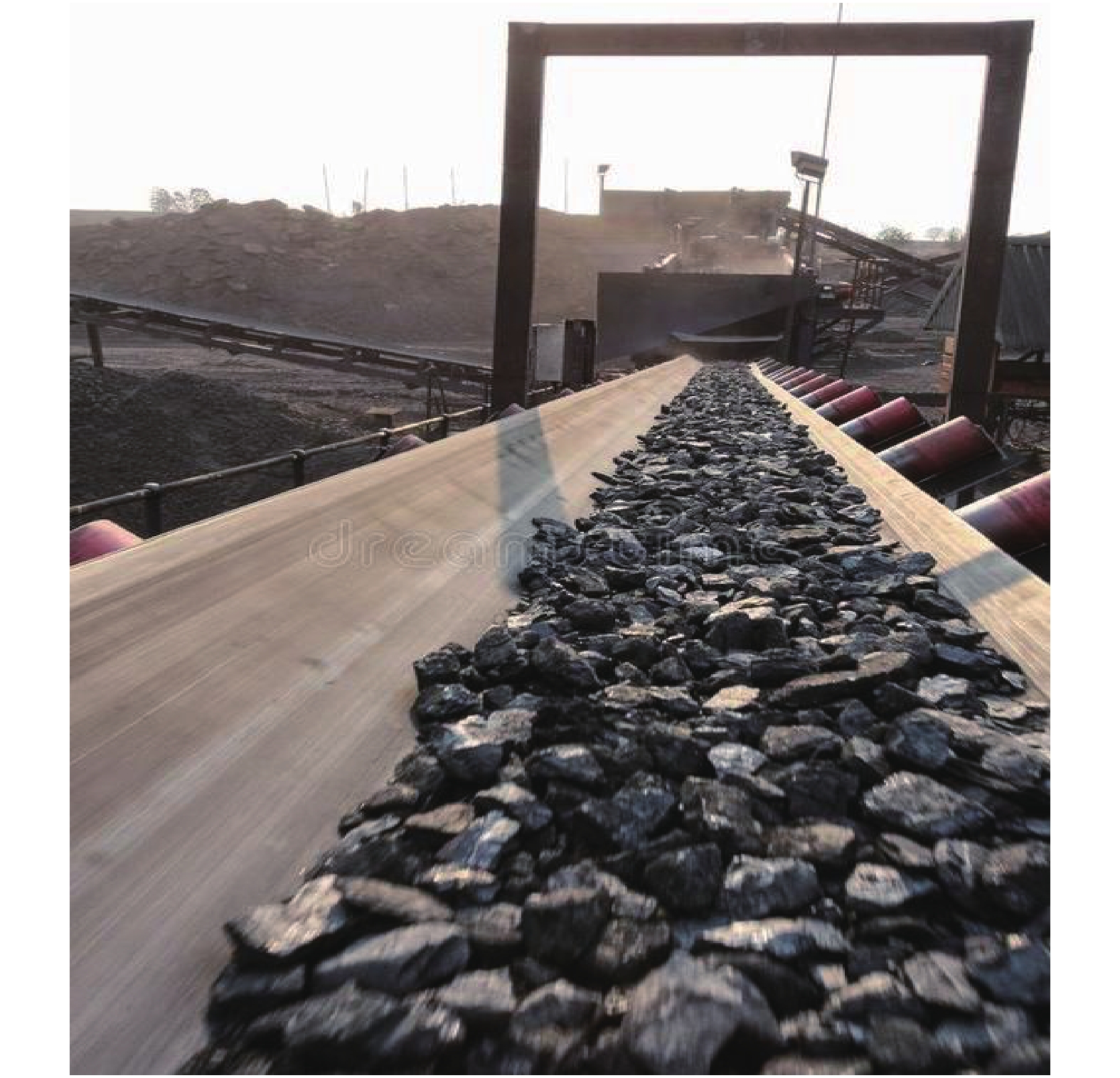
    Fig. 1. Ore transportation image on site
    Spectral intensity of solar radiation
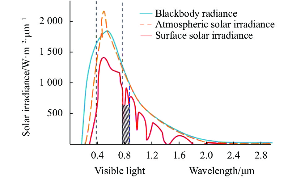
    Fig. 2. Spectral intensity of solar radiation
    Schematic diagram of infrared structured light ore image acquisition system
    Fig. 3. Schematic diagram of infrared structured light ore image acquisition system
    Ore images of visible and infrared structured light under different illumination conditions. (a) Green line laser (no direct sunlight); (b) Infrared laser (no direct sunlight); (c) Green line laser (strong light); (d) Infrared laser (strong light)
    Fig. 4. Ore images of visible and infrared structured light under different illumination conditions. (a) Green line laser (no direct sunlight); (b) Infrared laser (no direct sunlight); (c) Green line laser (strong light); (d) Infrared laser (strong light)
    Ideal gray distribution of line structured light cross section. (a) Ideal Gaussian distribution; (b) Flattened Gaussian distribution
    Fig. 5. Ideal gray distribution of line structured light cross section. (a) Ideal Gaussian distribution; (b) Flattened Gaussian distribution
    Gray distribution of visible and infrared structure cross section under different light environment. (a) Green line laser (no direct sunlight); (b) Infrared laser (no direct sunlight); (c) Green line laser (strong light); (d) Infrared laser (strong light)
    Fig. 6. Gray distribution of visible and infrared structure cross section under different light environment. (a) Green line laser (no direct sunlight); (b) Infrared laser (no direct sunlight); (c) Green line laser (strong light); (d) Infrared laser (strong light)
    Schematic diagram of sliding differential template. (a) Backward; (b) Forward
    Fig. 7. Schematic diagram of sliding differential template. (a) Backward; (b) Forward
    Forward cumulative difference
    Fig. 8. Forward cumulative difference
    Measurement of gauge block. (a) Schematic diagram of gauge block projection line; (b) Schematic diagram of height formation
    Fig. 9. Measurement of gauge block. (a) Schematic diagram of gauge block projection line; (b) Schematic diagram of height formation
    Extraction result of different method. (a) Gauss method; (b) Steger method; (c) Proposed method
    Fig. 10. Extraction result of different method. (a) Gauss method; (b) Steger method; (c) Proposed method
    Results of local center line deviation. (a) Gauss method; (b) Steger method; (c) Proposed method
    Fig. 11. Results of local center line deviation. (a) Gauss method; (b) Steger method; (c) Proposed method
    Endpoint centerline bifurcation by Steger method
    Fig. 12. Endpoint centerline bifurcation by Steger method
    Enlarged result in the yellow box in Fig.12. (a) Box A; (b) Box B; (c) Box C; (d) Box D
    Fig. 13. Enlarged result in the yellow box in Fig.12. (a) Box A; (b) Box B; (c) Box C; (d) Box D
    3D point cloud display and screening results of ore
    Fig. 14. 3D point cloud display and screening results of ore
    Column 761m=3 m=5 m=7 m=11
    Center point coordinates296.6066296.6066296.6308296.6308
    Table 1. Coordinates of the center point with different values of m (Unit: pixel)
    Gauge blockStandard block sizeProposed methodMeasurement errors
    H1100.02399.979−0.044
    H270.03169.997−0.034
    H339.99840.029+0.031
    Table 2. Height measurement results of the gauge block with proposed method (Unit: mm)
    Method/resultR2Off-line time/ms
    Gauss fitting0.956020.8
    Steger0.952628.6
    Proposed0.96584.9
    Table 3. Comparison of off-line structured light centerline extraction results
    Screening methodInfrared structured light 3D visionArtificial vision2D image processing[2-3]
    Light environmentComplex lightingDistinguish and clearlyModerate light
    Screening efficiency1-2 m/sInefficiencyAbout 0.4 m/s
    AccuracyHighLowInstable
    Automation degree100%ArtificialSemi-automatic
    SecuritySecurityUnsafeSecurity
    Table 4. Comprehensive comparison of online ore screening methods
    Xiuhua Zhang, Hanyu Hong, Yangyang Xu, Tianxu Zhang. Real time 3D vision screening method of ore under complex lighting conditions[J]. Infrared and Laser Engineering, 2021, 50(11): 20210125
    Download Citation