• Laser & Optoelectronics Progress
  • Vol. 58, Issue 20, 2011003 (2021)
Le Yang*, Shiqing Ren, Dongxiu Jiao, Xiaofen Geng, and Jianqiang Shen
Author Affiliations
  • College of Media Technology, Communication University of Shanxi, Jinzhong, Shanxi 030013, China
  • show less
    DOI: 10.3788/LOP202158.2011003 Cite this Article Set citation alerts
    Le Yang, Shiqing Ren, Dongxiu Jiao, Xiaofen Geng, Jianqiang Shen. Light Field Three-Dimensional Display with Super Multiple Viewpoints and Large Viewing Angle[J]. Laser & Optoelectronics Progress, 2021, 58(20): 2011003 Copy Citation Text show less
    Configuration of proposed light field 3D display device based on DLLA
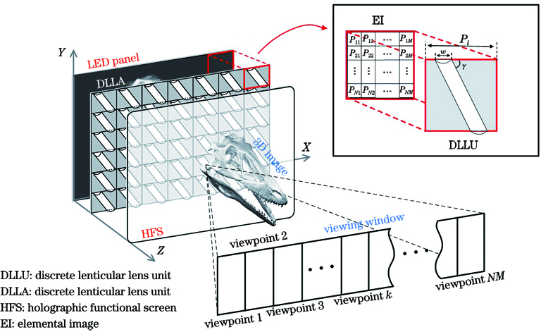
    Fig. 1. Configuration of proposed light field 3D display device based on DLLA
    Schematic diagram of construction of viewpoint light rays with EI and DLLU
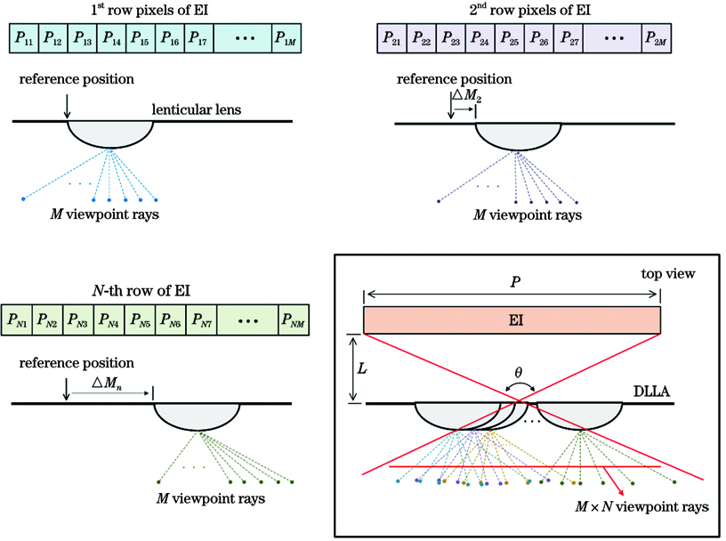
    Fig. 2. Schematic diagram of construction of viewpoint light rays with EI and DLLU
    Schematic diagram of horizontal light-field formation with DLLA
    Fig. 3. Schematic diagram of horizontal light-field formation with DLLA
    Schematic diagram of eliminating blind area of 3D image generated by DLLA with HFS
    Fig. 4. Schematic diagram of eliminating blind area of 3D image generated by DLLA with HFS
    Results of optical optimization design. (a) Designed structure of aspheric double-sided lenticular lens with optimized aberration; (b) comparison of spot diagrams of standard lenticular lens and optimized lenticular lens
    Fig. 5. Results of optical optimization design. (a) Designed structure of aspheric double-sided lenticular lens with optimized aberration; (b) comparison of spot diagrams of standard lenticular lens and optimized lenticular lens
    Light field 3D display prototype based on DLLA, and enlarged view of partial structure of DLLA. (a) Light field 3D display prototype based on DLLA; (b) enlarged view of partial structure of DLLA
    Fig. 6. Light field 3D display prototype based on DLLA, and enlarged view of partial structure of DLLA. (a) Light field 3D display prototype based on DLLA; (b) enlarged view of partial structure of DLLA
    Comparison of display effects obtained by using two light-controlled components. (a) Display effect obtained by using MPUA; (b) display effect obtained by using DLLA
    Fig. 7. Comparison of display effects obtained by using two light-controlled components. (a) Display effect obtained by using MPUA; (b) display effect obtained by using DLLA
    Comparison of display luminance obtained by using two light-controlled components. (a) Display luminance obtained by using MPUA; (b) display luminance obtained by using DLLA
    Fig. 8. Comparison of display luminance obtained by using two light-controlled components. (a) Display luminance obtained by using MPUA; (b) display luminance obtained by using DLLA
    Distortion analysis of optimized DLLA. (a) Schematic diagram of acquisition of light field from calibration board using camera array; (b) comparison of 3D imaging distortions of DLLAs assembled using standard lens and aspheric double-sided lenticular lens
    Fig. 9. Distortion analysis of optimized DLLA. (a) Schematic diagram of acquisition of light field from calibration board using camera array; (b) comparison of 3D imaging distortions of DLLAs assembled using standard lens and aspheric double-sided lenticular lens
    Views of 3D image from different directions within 42.8° viewing zone. (a) Angle: left 21.4°; (b) angle: left 10.7°; (c) angle: middle 0°; (d) angle: right 10.7°; (e) angle: right 21.4°
    Fig. 10. Views of 3D image from different directions within 42.8° viewing zone. (a) Angle: left 21.4°; (b) angle: left 10.7°; (c) angle: middle 0°; (d) angle: right 10.7°; (e) angle: right 21.4°
    Principal componentParameterValue
    LED displayScreen size /inch54 (diagonal)
    Resolution /pixel1280 (horizontal)×720 (vertical)
    MPUAPitch /mm9.30
    Minor axis length of micro-pinhole /mm0.183
    Major axis length of micro-pinhole /mm0.826
    Horizontal distance between adjacent pinholes /mm1.071
    Included angle between line connecting pinholes in PU and vertical line /(°)39.6
    Distance between LED panel and MPUA /mm16.332
    EIResolution /pixel10 (horizontal)×10 (vertical)
    HFSHorizontal diffused angle /(°)0.907
    Vertical diffused angle /(°)1.35
    Distance between HFS and MPUA /mm400
    Table 1. Parameters of light field 3D display prototype based on MPUA
    Principal componentParameterValue
    LED displayScreen size /inch54 (diagonal)
    Resolution /pixel1280 (horizontal)×720 (vertical)
    DLLAPitch /mm9.30
    Aperture of lenticular lens /mm1.86
    Slant angle of lenticular lens /(°)11.31
    Distance between LED panel and DLLA /mm11.87
    EIResolution /pixel10 (horizontal)×10 (vertical)
    HFSHorizontal diffused angle /(°)1.42
    Vertical diffused angle /(°)1.35
    Distance between HFS and DLLA /mm300
    Camera arrayNumber of cameras100
    Interval between cameras /mm18.02
    Field of view of camera /(°)14.75
    Resolution of camera /pixel1280 (horizontal)×720 (vertical)
    Table 2. Parameters of light field 3D display prototype based on DLLA
    Le Yang, Shiqing Ren, Dongxiu Jiao, Xiaofen Geng, Jianqiang Shen. Light Field Three-Dimensional Display with Super Multiple Viewpoints and Large Viewing Angle[J]. Laser & Optoelectronics Progress, 2021, 58(20): 2011003
    Download Citation