• Photonics Research
  • Vol. 10, Issue 12, 2677 (2022)
Juncheng Fang1、†, Jingbo Hu1、†, Yanan Zhong1, Aru Kong1, Jianxin Ren2, Shibiao Wei1, Zhenwei Xie1, Ting Lei1, Bo Liu2、3, and Xiaocong Yuan1、*
Author Affiliations
  • 1Nanophotonics Research Centre, Shenzhen Key Laboratory of Micro-Scale Optical Information Technology & Institute of Microscale Optoelectronics, Shenzhen University, Shenzhen 518060, China
  • 2Institute of Optoelectronics, Nanjing University of Information Science & Technology, Nanjing 210044, China
  • 3e-mail:
  • show less
    DOI: 10.1364/PRJ.465174 Cite this Article Set citation alerts
    Juncheng Fang, Jingbo Hu, Yanan Zhong, Aru Kong, Jianxin Ren, Shibiao Wei, Zhenwei Xie, Ting Lei, Bo Liu, Xiaocong Yuan. 3D waveguide device for few-mode multi-core fiber optical communications[J]. Photonics Research, 2022, 10(12): 2677 Copy Citation Text show less
    3D waveguide device and few-mode seven-core fiber. (a) One side of the 3D waveguide device is a waveguide array. (b) Top view of the 3D waveguide device. (c) Side view of the 3D waveguide device. (d) The other side of the 3D waveguide device is a seven-core arrangement.
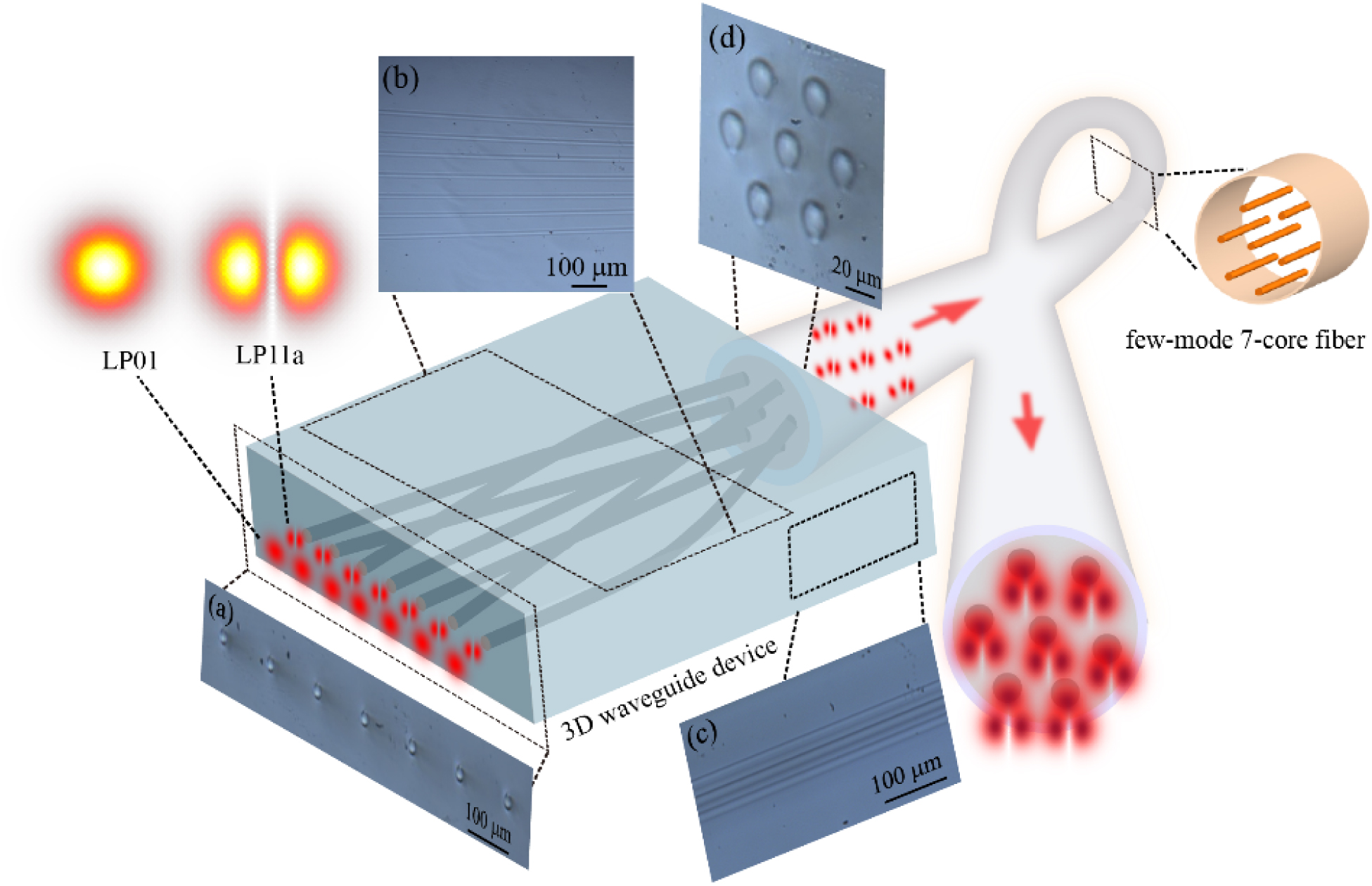
    Fig. 1. 3D waveguide device and few-mode seven-core fiber. (a) One side of the 3D waveguide device is a waveguide array. (b) Top view of the 3D waveguide device. (c) Side view of the 3D waveguide device. (d) The other side of the 3D waveguide device is a seven-core arrangement.
    Numerically simulated effect of (a) different effective refractive index differences for a 3D waveguide length of 17 mm and (b) bending curvature on the waveguide transmission efficiency when the effective refractive index difference is 0.0026. Numerically simulated (c) LP01 mode and (d) LP11a mode distributions at different positions in the 3D waveguide device.
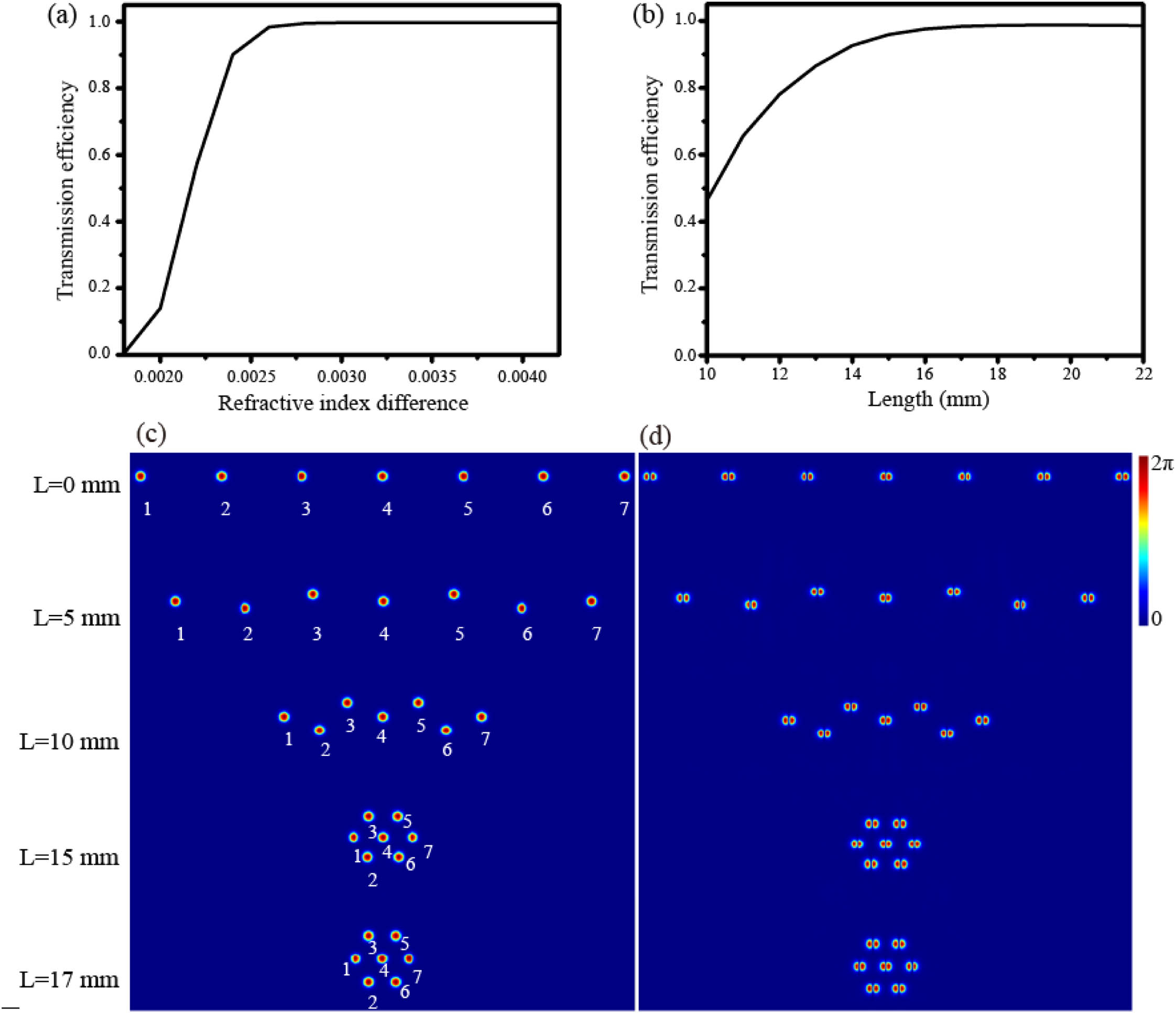
    Fig. 2. Numerically simulated effect of (a) different effective refractive index differences for a 3D waveguide length of 17 mm and (b) bending curvature on the waveguide transmission efficiency when the effective refractive index difference is 0.0026. Numerically simulated (c) LP01 mode and (d) LP11a mode distributions at different positions in the 3D waveguide device.
    Experimental intensity profiles of the (a) LP01 mode and (b) LP11a mode outputs from the 3D waveguide device. (c) Few-mode seven-core fiber. (d) Experimental setup of the few-mode fiber array coupled to an FM-MCF. Experimental intensity profiles of the (e) LP01 mode and (f) LP11a mode outputs from the few-mode seven-core fiber. (g) LP01 and LP11a modes insertion losses from the few-mode fiber array to the few-mode seven-core fiber.
    Fig. 3. Experimental intensity profiles of the (a) LP01 mode and (b) LP11a mode outputs from the 3D waveguide device. (c) Few-mode seven-core fiber. (d) Experimental setup of the few-mode fiber array coupled to an FM-MCF. Experimental intensity profiles of the (e) LP01 mode and (f) LP11a mode outputs from the few-mode seven-core fiber. (g) LP01 and LP11a modes insertion losses from the few-mode fiber array to the few-mode seven-core fiber.
    Measured cross talk between different waveguides when the (a) LP01 mode, (b) LP11a mode, and (c) LP11b mode propagate in the waveguide. Measured cross talk between different fiber cores when the (d) LP01 mode, (e) LP11a mode, and (f) LP11b mode propagate in the 1-km few-mode seven-core fiber.
    Fig. 4. Measured cross talk between different waveguides when the (a) LP01 mode, (b) LP11a mode, and (c) LP11b mode propagate in the waveguide. Measured cross talk between different fiber cores when the (d) LP01 mode, (e) LP11a mode, and (f) LP11b mode propagate in the 1-km few-mode seven-core fiber.
    (a) The setup of SDM communication system based on the few-mode seven-core fiber; TX, transmitter; SMF, single-mode fiber; PC, polarization controller; VOA, variable optical attenuator; EDFA, erbium-doped fiber amplifier; RX, receiver, PED, programmable error detector. Bit error rate (BER) curves of (b) cores 3 and 4, (c) cores 3 and 6, (d) cores 1 and 5.
    Fig. 5. (a) The setup of SDM communication system based on the few-mode seven-core fiber; TX, transmitter; SMF, single-mode fiber; PC, polarization controller; VOA, variable optical attenuator; EDFA, erbium-doped fiber amplifier; RX, receiver, PED, programmable error detector. Bit error rate (BER) curves of (b) cores 3 and 4, (c) cores 3 and 6, (d) cores 1 and 5.
    (a) The setup of SDM QPSK communication system based on the few-mode seven-core fiber. Constellations of the QPSK signals: (b) with fiber cores 3 of LP11a mode; (c) with fiber cores 3 of LP01 mode; (d) with fiber cores 4 of LP11a mode; (e) with fiber cores 4 of LP01 mode.
    Fig. 6. (a) The setup of SDM QPSK communication system based on the few-mode seven-core fiber. Constellations of the QPSK signals: (b) with fiber cores 3 of LP11a mode; (c) with fiber cores 3 of LP01 mode; (d) with fiber cores 4 of LP11a mode; (e) with fiber cores 4 of LP01 mode.
    Fabrication setup for 3D waveguide devices based on femtosecond laser direct writing.
    Fig. 7. Fabrication setup for 3D waveguide devices based on femtosecond laser direct writing.
    (a) The effective refractive index difference versus radius of a fiber core in FM-MCF. Numerical simulation calculations show that the FM-MCF supports (b) LP01, (c) LP11a or LP11b, (d) LP21a or LP21b, (e) LP02, (f) LP31a or LP31b, (g) LP12a or LP12b modes transmission.
    Fig. 8. (a) The effective refractive index difference versus radius of a fiber core in FM-MCF. Numerical simulation calculations show that the FM-MCF supports (b) LP01, (c) LP11a or LP11b, (d) LP21a or LP21b, (e) LP02, (f) LP31a or LP31b, (g) LP12a or LP12b modes transmission.
    Channel1234567
    LP010.99900.99910.99910.99990.99910.99910.9990
    P11a0.99680.99800.99860.99980.99860.99800.9968
    Table 1. Calculated Transmission Efficiencies of LP01 and LP11a in Different Waveguides
    Juncheng Fang, Jingbo Hu, Yanan Zhong, Aru Kong, Jianxin Ren, Shibiao Wei, Zhenwei Xie, Ting Lei, Bo Liu, Xiaocong Yuan. 3D waveguide device for few-mode multi-core fiber optical communications[J]. Photonics Research, 2022, 10(12): 2677
    Download Citation