
Juncheng Fang, Jingbo Hu, Yanan Zhong, Aru Kong, Jianxin Ren, Shibiao Wei, Zhenwei Xie, Ting Lei, Bo Liu, Xiaocong Yuan, "3D waveguide device for few-mode multi-core fiber optical communications," Photonics Res. 10, 2677 (2022)
- Photonics Research
- Vol. 10, Issue 12, 2677 (2022)
Abstract
1. INTRODUCTION
With the rapid development of network traffic, existing single-mode fiber communication technology has approached the nonlinear Shannon limit of 100 Tbit/s [1]. Space-division multiplexing (SDM) with multi-core fibers (MCFs) [2,3] and few-mode fibers (FMFs) [4,5] is one of the most promising approaches to breaking the capacity limit. SDM increases fiber capacity using a spatial channel as an additional multiplexing degree of freedom [6–8]. MCF contains multiple single-mode fiber cores, each of which represents an independent information channel. FMF uses orthogonal modes of different orders such as linearly polarized (LP) [9,10], orbital angular momentum [11–13], and cylindrical vector beam modes [14,15] as independent channels to increase fiber capacity. Optical geometric transformation [15–18] and multi-plane light conversion (MPLC) [19–22] provide efficient mode multiplexing/demultiplexing for communication. Currently, single-mode MCFs with more than 30 cores have been demonstrated [23], and FMF transmission with more than 10 modes has been used to increase fiber capacity [24,25]. However, the diameter of MCF is between 125 and 318 μm, and the different cores need to be kept distant from each other to limit inter-core cross talk, thus limiting the number of cores in the MCF [26]. Moreover, the number of modes used in FMF transmission is limited by the effective refractive index difference between a fiber core and its surroundings [27]. To further increase the fiber capacity, focus has recently turned to combining the MCF and FMF into a few-mode multi-core fiber (FM-MCF) [28]. SDM communication systems with more than 100 spatial channels have been demonstrated in FM-MCFs with data rates exceeding 10 Pb/s [29,30]. While FM-MCFs promise to significantly increase fiber capacity, eventual deployment of FM-MCF networks still requires practical methods to couple individual modes into closely spaced fiber cores.
Besides optical fibers, fan-outs or other means of combining and separating the various spatial paths are needed for SDM based on FM-MCFs. In recent years, several coupling methods have been proposed for FM-MCFs, such as free space coupling [31], photonic wire bonding [32], fused tapers [33], and 3D waveguide devices [34–36]. Photonic integrated devices show great potential in optical fiber communication [37], sensing [38], imaging [39,40], and quantum information systems [41], especially in combining and separating dense FM-MCF cores [42]. For an SDM system that includes an FM-MCF, a photonic integrated device is indispensable to realizing the optical interconnection between the FMF and FM-MCF. The 3D waveguide device is a photonic integrated device fabricated by femtosecond laser direct writing [43,44] that provides a low insertion loss, low cross talk, and small-size solution for an FM-MCF. The 3D waveguide device consists of multiple waveguides, each of which corresponds to one of the cores of the FM-MCF. Multiple waveguides are spatially bent to separate the closely spaced FM-MCF cores and couple the LP modes into these cores. Propagation of higher-order modes in the waveguide requires a larger effective refractive index difference between the waveguide and the cladding to confine the beam. Therefore, the performance of an FM-MCF communication system based on a 3D waveguide is related to the number of supported modes in the waveguide, the insertion loss between the waveguide and the fiber, and the cross talk between different waveguides.
In this paper, we propose and demonstrate a 3D waveguide device for FM-MCF optical communications. The device is fabricated by laser direct writing. Each waveguide supports LP01, LP11a, and LP11b modes transmission at a wavelength of 1550 nm, and has a diameter of 16.5 μm and an effective refractive index difference larger than 0.0026 with the surrounding material. One side of the 3D waveguide device is a one-dimensional waveguide array composed of seven waveguides with a pitch of 127 μm, and the other side is a seven-core distribution matched to a few-mode seven-core fiber. An MPLC system outputs multiple groups of LP01, LP11a, and LP11b modes that are transmitted in a 3D waveguide device, and the cross talk between different waveguides is less than
Sign up for Photonics Research TOC. Get the latest issue of Photonics Research delivered right to you!Sign up now
2. 3D WAVEGUIDE DESIGN AND FABRICATION
Figure 1 shows the schematic of the 3D waveguide device for FM-MCF coupling. One side of the device is a one-dimensional array of seven waveguides with a pitch of 127 μm for interconnection with the few-mode fiber array [Fig. 1(a)]. The one-dimensional waveguide array is gradually bent in a 3D waveguide device to converge to the central waveguide. Figure 1(b) shows the waveguide array convergence. Viewed from the side of the 3D wave device, multiple waveguides will converge, as shown in Fig. 1(c). Figure 1(d) shows the other side of the 3D waveguide device is a seven-core waveguide structure with six waveguides surrounding the central waveguide with a radius of 42 μm and a spacing of 60°, matching the few-mode seven-core fiber. The waveguide array is bent between the two sides of the 3D waveguide device. After sizing the 3D waveguide device, we optimized the waveguide bending curve to reduce mode leakage, cross talk, and transmission loss, and to determine the device selection. The detailed theory of the S-bend design for 3D waveguide performance optimization was well explained by the literature previously [45,46]. The bending of the waveguide is optimized with the function
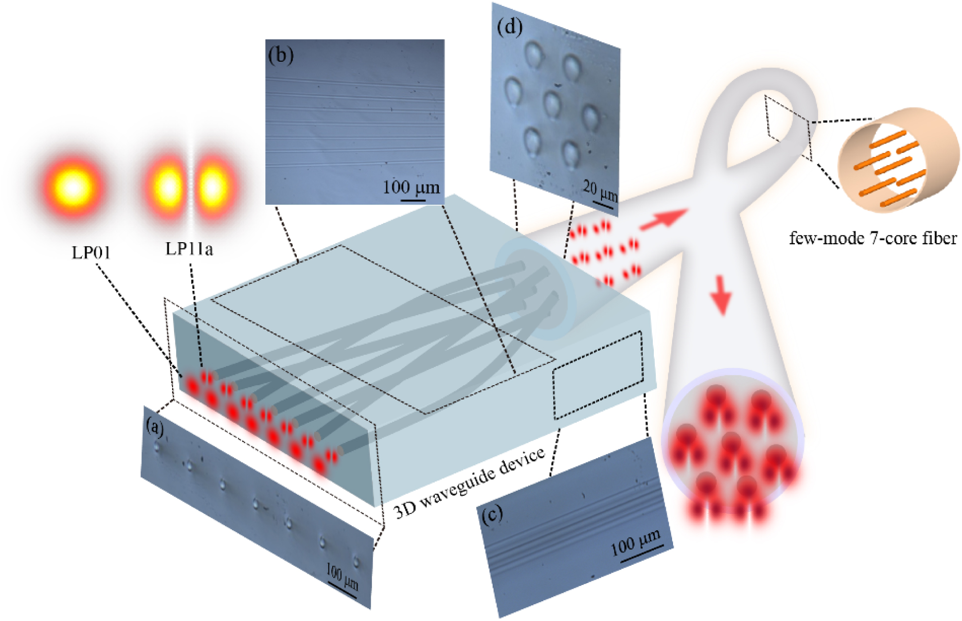
Figure 1.3D waveguide device and few-mode seven-core fiber. (a) One side of the 3D waveguide device is a waveguide array. (b) Top view of the 3D waveguide device. (c) Side view of the 3D waveguide device. (d) The other side of the 3D waveguide device is a seven-core arrangement.
![]()
Figure 2.Numerically simulated effect of (a) different effective refractive index differences for a 3D waveguide length of 17 mm and (b) bending curvature on the waveguide transmission efficiency when the effective refractive index difference is 0.0026. Numerically simulated (c) LP01 mode and (d) LP11a mode distributions at different positions in the 3D waveguide device.
The simulation of the LP11a mode considers the bending of the waveguide, and the light spot distribution at different positions in the waveguide is observed by the established bending waveguide model. Figures 2(c) and 2(d) show numerically simulated LP01 and LP11a modes propagating in a 3D waveguide device with each waveguide marked. We calculated the cross talk between different waveguides when the length of the 3D waveguide device is 17 mm and the effective refractive index difference is 0.004. The numerical simulation shows that the cross talk between different waveguides is less than
Calculated Transmission Efficiencies of LP01 and LP11a in Different Waveguides
| Channel | 1 | 2 | 3 | 4 | 5 | 6 | 7 |
|---|---|---|---|---|---|---|---|
| LP01 | 0.9990 | 0.9991 | 0.9991 | 0.9999 | 0.9991 | 0.9991 | 0.9990 |
| P11a | 0.9968 | 0.9980 | 0.9986 | 0.9998 | 0.9986 | 0.9980 | 0.9968 |
Femtosecond lasers have the advantages of ultra-short pulse duration and high peak intensity, providing a solution for 3D waveguide device fabrication. The 3D waveguide devices in our experiments were fabricated by femtosecond laser direct writing. The setup of the femtosecond laser direct writing is shown in Appendix A. When a femtosecond laser is focused on the fabricated substrate, the refractive index of the focal region changes permanently owing to the rapid absorption of laser energy via nonlinear mechanisms. The area where the femtosecond laser is focused has a refractive index difference with the material of the surrounding substrate, which is used for the light beam transmission. The design of the 3D waveguide device was optimized by adjusting various parameters such as repetition rate, pulse width, material properties, and depth of focus. We then chose a femtosecond laser with a wavelength of 1030 nm, pulse width of 180 fs, single pulse energy of 200 nJ, and repetition rate of 200 kHz. The 3D waveguide device was fabricated by focusing a femtosecond laser at 150 μm below the glass surface with a
3. EXPERIMENTAL RESULTS AND ANALYSIS
In the experiments, multiple LP modes were generated by MPLC and coupled to one side of the 3D waveguide device by a one-dimensional few-mode fiber array. The multiple LP modes were output from the other side of the 3D waveguide device, as shown in Figs. 3(a) and 3(b). In the experiments, the LP modes of the seven cores are generated by seven individual MPLC LP mode multiplexers [21]. The MPLC has coaxial output of LP modes in few-mode fiber as the input modes coupling to the waveguides. Any perturbation or bending of the fiber will cause the LP11a mode rotation. Therefore, the input and the output LP11a modes have various rational deviations from the horizontal direction. Figure 3(c) shows the few-mode seven-core fiber (the few-mode seven-core fiber supports six LP mode transmissions, as shown in Appendix B). The distribution of the light beam output from the 3D waveguide device is consistent with the core distribution of the few-mode seven-core fiber. We then coupled the light beam output of the 3D waveguide device to a few-mode seven-core fiber using the experimental setup in Fig. 3(d). Figures 3(e) and 3(f) show the LP01 and LP11a modes output from the 1-km few-mode seven-core fiber. The insertion losses of the LP01 and LP11a modes from the few-mode fiber array to the few-mode seven-core fiber are less than 1.7 dB and 2.7 dB, respectively, including the insertion losses from the few-mode fiber to the 3D waveguide device and the 3D waveguide device to the few-mode seven-core fiber. Numerical simulations show that the insertion loss of the LP01 mode is increased by 0.3 dB and that of the LP11a mode by 1 dB owing to the mismatch in refractive index distributions of the waveguide and the fiber. Figure 3(g) shows the insertion losses of LP01 and LP11a modes coupled to seven cores. In addition, the return loss of the fiber-waveguide is measured as less than
![]()
Figure 3.Experimental intensity profiles of the (a) LP01 mode and (b) LP11a mode outputs from the 3D waveguide device. (c) Few-mode seven-core fiber. (d) Experimental setup of the few-mode fiber array coupled to an FM-MCF. Experimental intensity profiles of the (e) LP01 mode and (f) LP11a mode outputs from the few-mode seven-core fiber. (g) LP01 and LP11a modes insertion losses from the few-mode fiber array to the few-mode seven-core fiber.
As the beam propagates in the 3D waveguide device or FM-MCF, the beam leaks, and the leaked beam causes cross talk in different waveguides or the fiber core. Therefore, we measured the cross talk of LP01, LP11a, and LP11b modes propagating in the waveguide and few-mode seven-core fiber. Figures 4(a), 4(b), and 4(c) show the cross talks of the LP01, LP11a, and LP11b modes propagating in the 3D waveguide, respectively. The different waveguide cross talk of the LP01, LP11a, and LP11b modes are less than
![]()
Figure 4.Measured cross talk between different waveguides when the (a) LP01 mode, (b) LP11a mode, and (c) LP11b mode propagate in the waveguide. Measured cross talk between different fiber cores when the (d) LP01 mode, (e) LP11a mode, and (f) LP11b mode propagate in the 1-km few-mode seven-core fiber.
In communication experiments, we demonstrated four-channel multiplexed communication with two LP modes and two cores in a 1-km few-mode seven-core fiber via a 3D waveguide device. Figure 5(a) shows the experimental setup with four Gaussian beams output from four commercial optical modules, with each channel carrying a 10-Gbit/s on–off keying (OOK) signal. Four Gaussian beams carrying OOK signals are input from single-mode fibers to two MPLC systems [21]. Each MPLC system converts two of the four Gaussian modes into an LP01 and an LP11a modes for coaxial transmission in few-mode fibers. Two few-mode fibers form a few-mode fiber array and are simultaneously coupled to the 3D waveguide device. Two few-mode fibers correspond to two respective waveguides and are coupled to the two fiber cores of the few-mode seven-core fiber. Two light beams are transmitted in a 1-km few-mode seven-core fiber and coupled to the two few-mode fibers by another 3D waveguide device. Two few-mode fibers are respectively input to two MPLC systems. Each MPLC system converts the LP01 and LP11a modes in the few-mode fibers into two Gaussian beams at different positions, which are coupled to the single-mode fibers for error detection. In experiments, we demonstrated three groups of bit error detections for different fiber core combinations to determine the effects of different degrees of bending of the waveguide and different fiber core positions on the BER. The three FM-MCF core combinations are 3 and 4, 3 and 6, 1 and 5, and the fiber core numbers are marked as shown in Fig. 2(c). The power penalties of the three groups of BER curves in Figs. 5(b)–5(d) are all less than 13 dB, including the MPLC system, 3D waveguide device, and FM-MCF. The power penalty of Figs. 5(b) and 5(c) is about 1 dB less than that of Fig. 5(d), which is attributed to the larger waveguide bending in channels 1 and 5. The insertion loss between the FM-MCF and 3D waveguide device is 3 dB, resulting in a shorter BER curve and larger power penalty for the 1-km FM-MCF. For visualization purposes, we also measured the constellations of the four channels carrying 10-Gbit/s QPSK signals consisting of two LP modes and two cores, the setup as shown in Figs. 6(a). Figures 6(b)–6(e) show the constellations with the fiber cores 3 of LP11a mode, the fiber cores 3 of LP01 mode, the fiber cores 4 of LP11a mode, and the fiber cores 4 of LP01 mode, respectively. We can see that there is some overlap in the constellations, which can be corrected by the algorithm. These communication experiments demonstrate that the 3D waveguide device provides a solution for FM-MCF coupling, and SDM based on the 3D waveguide device and the FM-MCF can greatly improve fiber capacity. Theoretically, each core of a few-mode seven-core fiber transmits two LP modes, which can increase the capacity by a factor of 14 compared with a single-mode fiber. In follow-up research, the FM-MCF capacity can be further improved by improving the waveguide fabrication process to enable the 3D waveguide device to support higher-order LP modes transmission.
![]()
Figure 5.(a) The setup of SDM communication system based on the few-mode seven-core fiber; TX, transmitter; SMF, single-mode fiber; PC, polarization controller; VOA, variable optical attenuator; EDFA, erbium-doped fiber amplifier; RX, receiver, PED, programmable error detector. Bit error rate (BER) curves of (b) cores 3 and 4, (c) cores 3 and 6, (d) cores 1 and 5.
![]()
Figure 6.(a) The setup of SDM QPSK communication system based on the few-mode seven-core fiber. Constellations of the QPSK signals: (b) with fiber cores 3 of LP11a mode; (c) with fiber cores 3 of LP01 mode; (d) with fiber cores 4 of LP11a mode; (e) with fiber cores 4 of LP01 mode.
4. CONCLUSION
In conclusion, we proposed and demonstrated a 3D waveguide device for few-mode multi-core fiber optical communications. The 3D waveguide device was fabricated by femtosecond laser direct writing, and supports LP01, LP11a, and LP11b modes transmission. We optimized the waveguide bending to reduce mode leakage and cross talk. The 3D waveguide device coupled multiple groups of LP01 and LP11a modes into a 1-km few-mode seven-core fiber with an insertion loss of less than 3 dB. In communication experiments, we demonstrated four-channel multiplexing communication in a few-mode seven-core fiber consisting of two LP modes and any two fiber cores. Theoretically, 14-channel multiplexing communication is possible with a 3D waveguide device and a few-mode seven-core fiber. The FM-MCF capacity can be further improved by increasing the number of channels in the FM-MCF, which mainly involves increasing the number of channels in the 3D waveguide device. The number of channels in the 3D waveguide device can be increased by increasing the waveguide diameter or the effective refractive index difference between the waveguide and surroundings. Numerical simulations show that when the refractive index difference is 0.004 and the waveguide diameter is 17.5 μm, the waveguide supports transmission up to the LP21 mode. When the waveguide diameter is 16.5 μm, we can increase the refractive index difference between the waveguide and the cladding to support the transmission of higher-order LP modes by increasing the repetition rate and pulse width of the femtosecond laser or changing the substrate. Improvements in waveguide fabrication processes can enable 3D waveguide devices to support higher-order LP-modes transmission and further increase FM-MCF capacity. SDM consisting of 3D waveguide devices and FM-MCFs is expected to realize ultra-high-capacity multiplexed communication.
Acknowledgment
Acknowledgment. The authors would like to acknowledge the Photonics Center of Shenzhen University for providing technical support.
APPENDIX A: FEMTOSECOND LASER DIRECT WRITING TO FABRICATE 3D WAVEGUIDE DEVICE
Figure
![]()
Figure 7.Fabrication setup for 3D waveguide devices based on femtosecond laser direct writing.
APPENDIX B: FEW-MODE SEVEN-CORE FIBER
We use the step-index FM-MCF for LP modes transmission with a core radius of 8.25 μm. Figure
![]()
Figure 8.(a) The effective refractive index difference versus radius of a fiber core in FM-MCF. Numerical simulation calculations show that the FM-MCF supports (b) LP01, (c) LP11a or LP11b, (d) LP21a or LP21b, (e) LP02, (f) LP31a or LP31b, (g) LP12a or LP12b modes transmission.
References
[2] R. S. Romaniuk. Multicore optical fibers. Rev. Roum. Phys., 32, 99-112(1987).
[3] K. Saitoh, S. Matsuo. Multicore fiber technology. J. Lightwave Technol., 34, 55-66(2016).
[30] D. Soma, Y. Wakayama, S. Beppu, S. Sumita, T. Tsuritani, T. Hayashi, T. Nagashima, M. Suzuki, M. Yoshida, K. Kasai, M. Nakazawa, H. Takahashi, K. Igarashi, I. Morita, M. Suzuki. 10.16-peta-b/s dense SDM/WDM transmission over 6-mode 19-core fiber across the C plus L band. J. Lightwave Technol., 36, 1368-1375(2018).
[33] V. I. Kopp, J. Park, J. Singer, D. Neugroschl, A. Gillooly. Low return loss multicore fiber-fanout assembly for SDM and sensing applications. Optical Fiber Communication Conference (OFC), M2C.3(2020).


Set citation alerts for the article
Please enter your email address

© Copyright 2018-2021 | Chinese Laser Press. All Rights Reserved 沪ICP备15018463号-20