
E ZHANG, Shuai-Shuai CHEN, Li-Yang ZHANG. The phenomena of lunar observation in cold space reference sampling area of Visible and Infrared Radiometer on FY-3 Meteorological Satellite [J]. Journal of Infrared and Millimeter Waves, 2020, 39(6): 802
- Journal of Infrared and Millimeter Waves
- Vol. 39, Issue 6, 802 (2020)
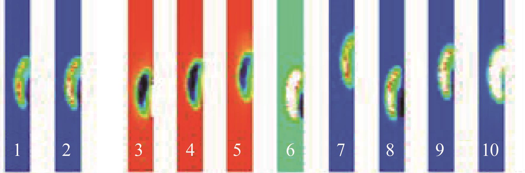
Fig. 1. 10 channels cold space sampling points of VIRR
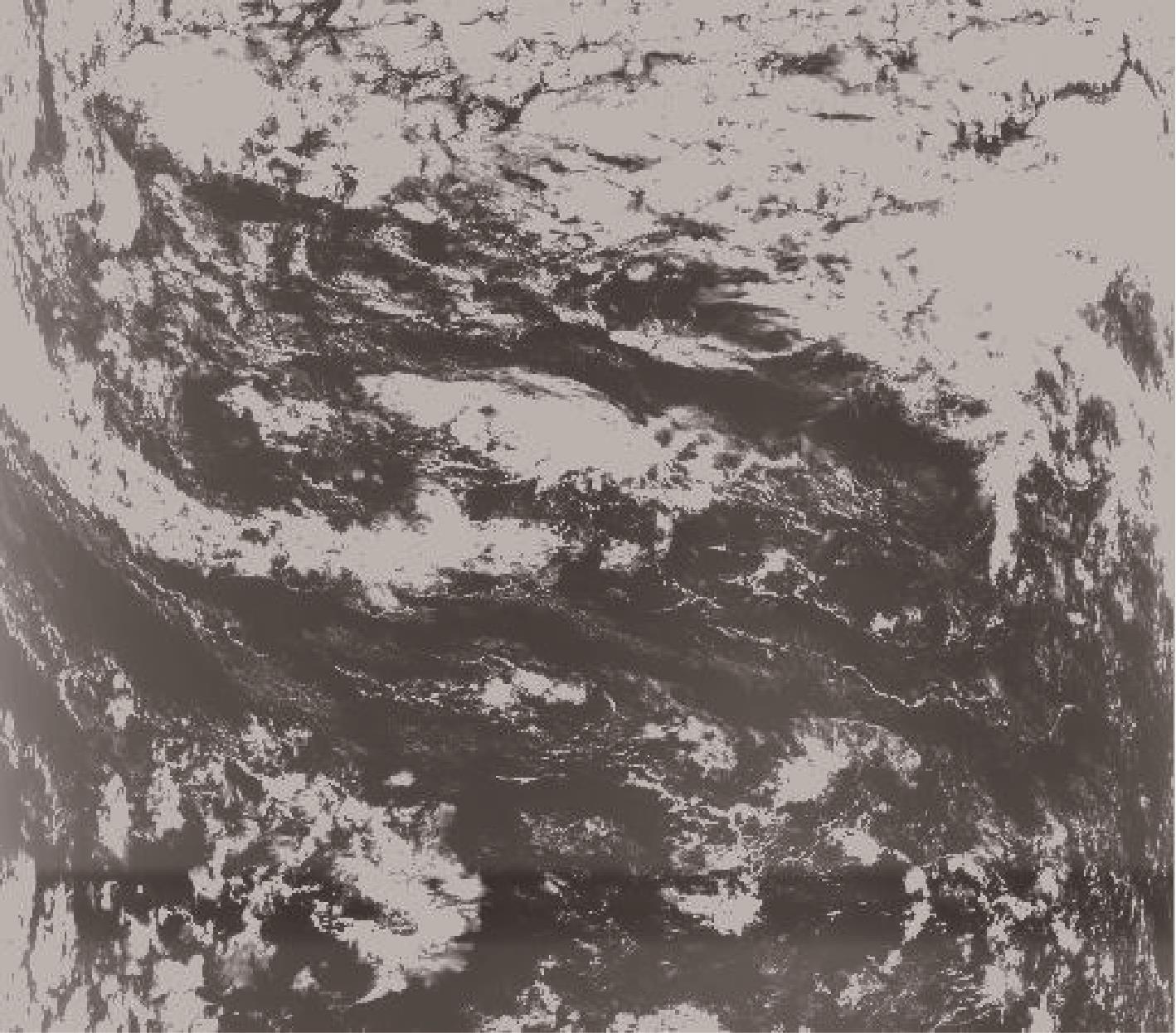
Fig. 2. Visible channel image of VIRR
Fig. 3. Image of VIRR infrared channel
Fig. 4. (a) Diagram of radiometer spatial scanning geometry, (b) radiometer signal acquisition angle position diagram
Fig. 5. Simulation of orbit position of earth, sun and moon
Fig. 6. Simulation of the angle between the moon and the nadir of scan radiometer
Fig. 7. Time simulation of the moon appearing in cold space in one year period of satellite operation
Fig. 8. Phase diagram of the moon observed by VIRR (a) Descent orbit 13:05, March 1, 2012, (b) ascent orbit 21:05 ,March 4, 2012
Fig. 9. Geometry diagram of 45° rotating scanning mirror scanning
Fig. 10. Diagram of channel registration and sampling sequence
Fig. 11. Diagram of FOV registration in image rotation
Fig. 12. Registration relationship of each FOV after image rotation and sampling sequence processing
Fig. 13. Cold space sampling image of each channel
Fig. 14. Scanning line position diagram of flight direction of CH7, 9, 6, 2 at lunar observation time
Fig. 15. Diagram of DC recovery circuit
Fig. 16. Earth area image of visible channel 1, (a)before data correction, (b)after data correction
Fig. 17. Earth area image of IR channel 4
|
Table 1. VIRR探测通道及探测光谱范围

Set citation alerts for the article
Please enter your email address
© Copyright 2018-2021 | Chinese Laser Press. All Rights Reserved 沪ICP备15018463号-20