
Kang-Cheng ZHOU, Jin-Jun FENG. Theory modification and design of elliptical quasi-optical mode converter for Ka-band quasi-TE01 mode[J]. Journal of Infrared and Millimeter Waves, 2021, 40(6): 754
- Journal of Infrared and Millimeter Waves
- Vol. 40, Issue 6, 754 (2021)
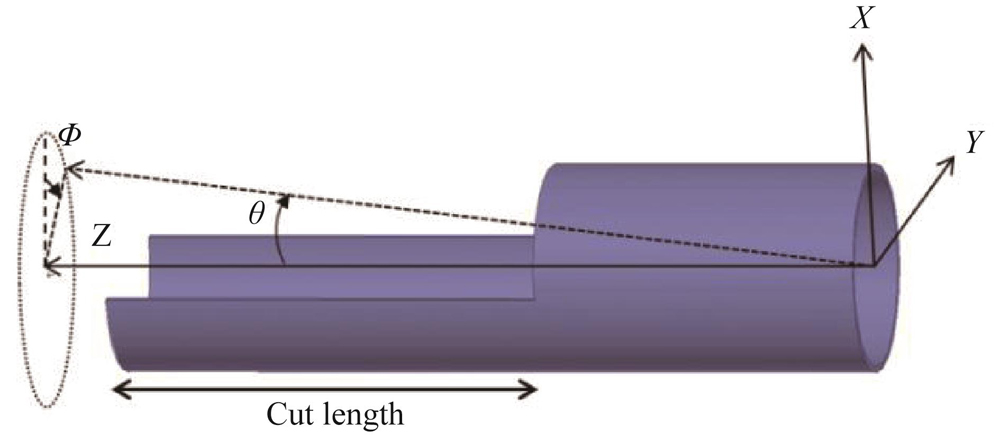
Fig. 1. Schematic diagram of the stepped circular waveguide Vlasov launcher,including the relative spatial relationship of the geometric parameters
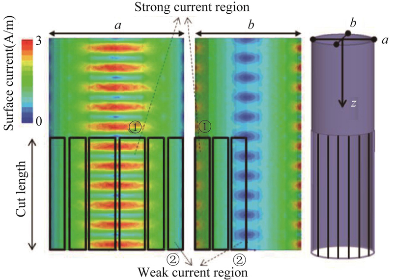
Fig. 2. Current distribution on the surface of elliptical waveguide,Note:The left side is the current distribution along the long axis,the middle is the current distribution along the short axis,and the right side is the schematic diagram of Vlasov launcher of stepped elliptical waveguide. The black rectangle represents the equivalent slot
Fig. 3. Relative percentage error between the radiation angle calculated by the correction formula and the simulation results under different correction factors
Fig. 4. The relationship between the main radiation angle θ and the radiation energy gain of elliptic system with different scale factors (ϕ = 0 ° in the figure)
Fig. 5. The relationship between the angle ϕ and the radiation energy gain for elliptic systems with different cut lengths (θ = 22.5 ° in the figure)
Fig. 6. (a) Schematic diagram of convergence effect of quasi-paraboiodal mirror, (b) Schematic diagram of geometrical optics of quasi-paraboiodal mirror
Fig. 7. (a) Comparison of far-field energy gain corresponding to principal radiation angle θ of elliptic system and circular system, (b) comparison in polar coordinate system
Fig. 8. Schematic diagram of relative position relationship between launcher with quasi parabolic mirror and output port
Fig. 9. (a)Electric field distribution comparison diagram,electric field distribution of circular waveguide radiator with quasi-paraboiodal mirror at output port,(b)Electric field distribution of elliptical waveguide radiator with quasi-paraboiodal mirror designed by modified formula at output port,(c)Ideal Gauss electric field distribution diagram

Set citation alerts for the article
Please enter your email address
© Copyright 2018-2021 | Chinese Laser Press. All Rights Reserved 沪ICP备15018463号-20