
Jiahui Li, Fenli Tan, Chenxin Zeng, Yiqun Ji. Design of Optical System for UAV-Borne Ultralow-Altitude Wide-Coverage Remote Sensing Camera[J]. Acta Optica Sinica, 2021, 41(14): 1422001
- Acta Optica Sinica
- Vol. 41, Issue 14, 1422001 (2021)
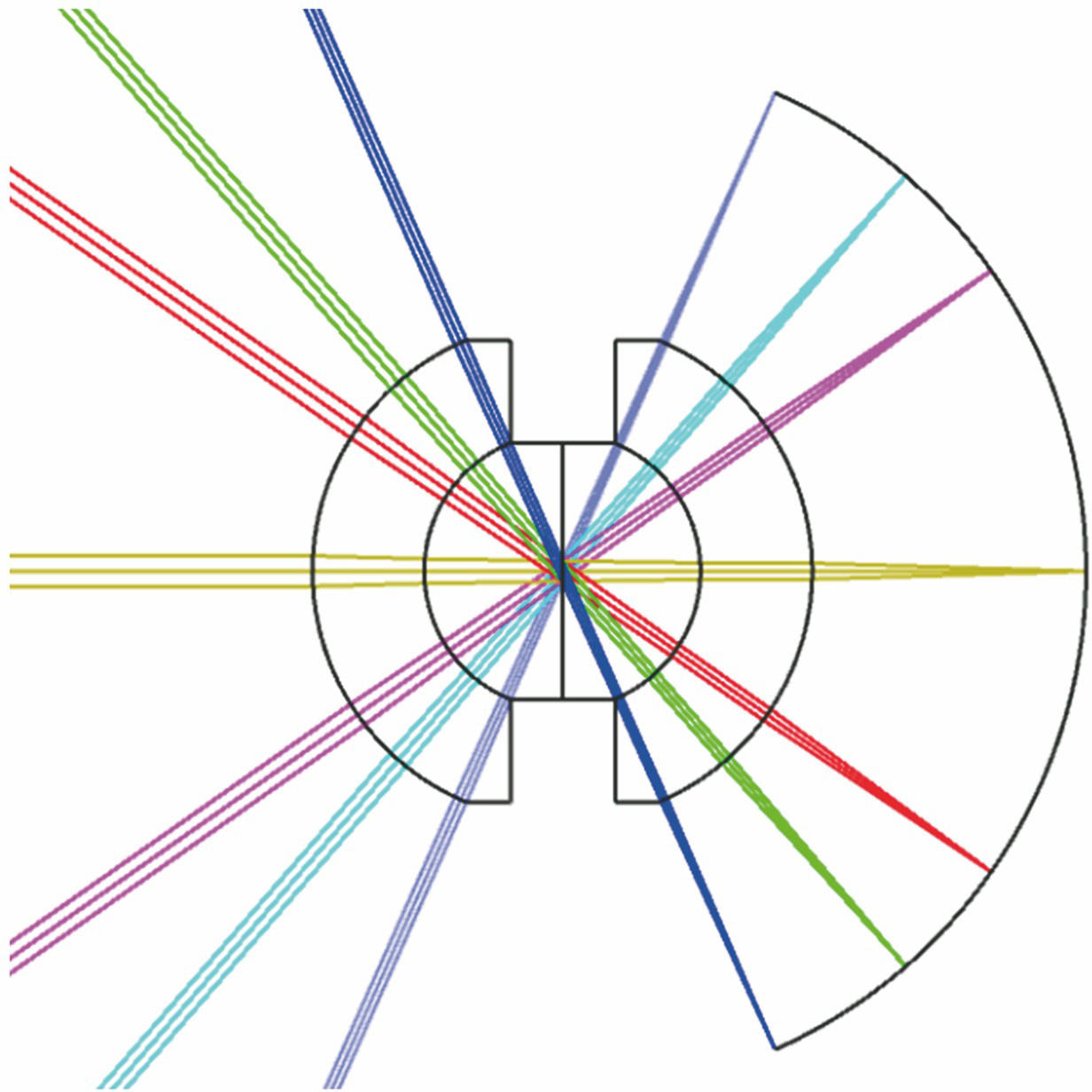
Fig. 1. Optical imaging diagram of monocentric symmetric objective
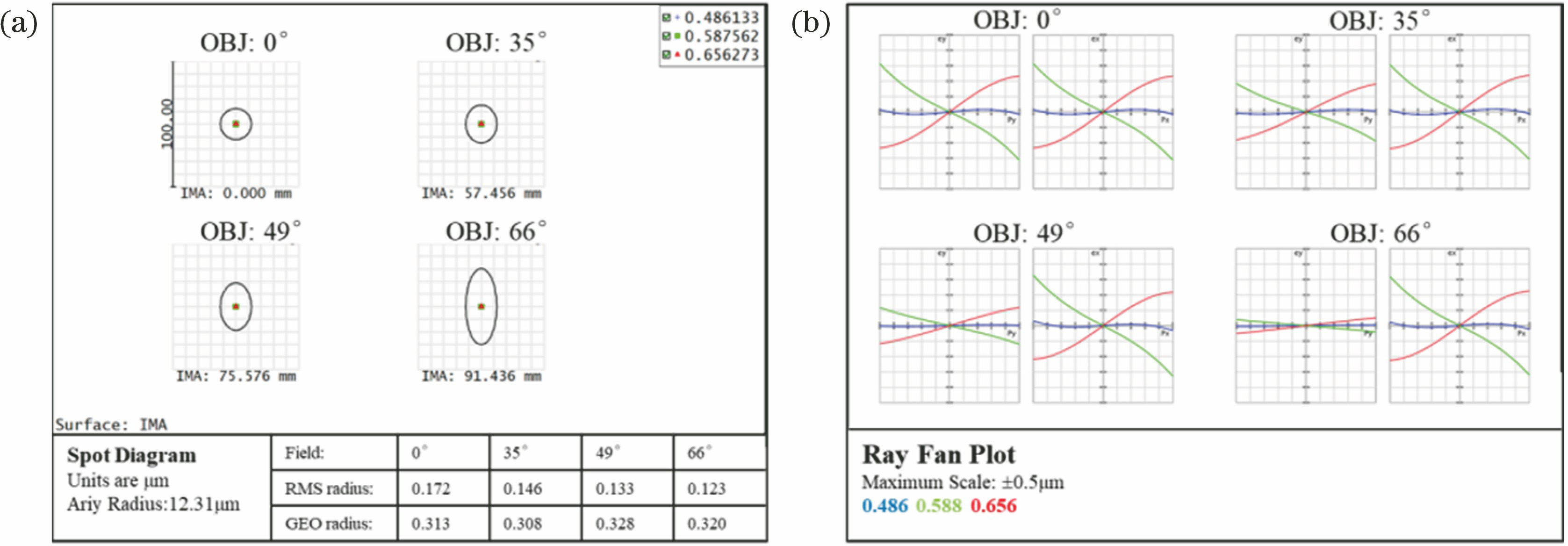
Fig. 2. Optical layout of monocentric symmetric objective
Fig. 3. Imaging performance of monocentric symmetric objective at the optimal image surface when the flight altitude is 50 m. (a) Spot diagram; (b) ray fan
Fig. 4. Optical layout of relay lens system
Fig. 5. Single-channel imaging optical layout
Fig. 6. MTF of single-channel imaging optical system at different flight altitudes. (a) 20 m; (b) 50 m; (c) 80 m
Fig. 7. Spot diagram of single-channel imaging optical system at different flight altitudes. (a) 20 m; (b) 50 m; (c) 80 m
Fig. 8. Field curvature/distortion curve of single-channel imaging optical system at different flight altitudes. (a) 20 m; (b) 50 m; (c) 80 m
Fig. 9. Multi-channel imaging optical layout
|
Table 1. Parameters in the intermediate image surface equation when the flight altitude is 50 m
| |||||||||||||||||||||||||||||||||||||||||||||||||||||
Table 2. Axial displacement of the optimal intermediate image surface at different flight altitudes relative to 50 m and evaluation results of the spot diagram
|
Table 3. Aspheric surface parameters

Set citation alerts for the article
Please enter your email address
© Copyright 2018-2021 | Chinese Laser Press. All Rights Reserved 沪ICP备15018463号-20