• Photonics Research
  • Vol. 4, Issue 2, 0035 (2016)
Rulei Xiao, Yuechun Shi*, Renjia Guo, Ting Chen, Lijun Hao, and Xiangfei Chen
Author Affiliations
  • National Laboratory of Solid State Microstructures, Collaborative Innovation Center of Advanced Microstructures, and College of Engineering and Applied Sciences, Nanjing University, Nanjing 210093, China
  • show less
    DOI: 10.1364/prj.4.000035 Cite this Article Set citation alerts
    Rulei Xiao, Yuechun Shi, Renjia Guo, Ting Chen, Lijun Hao, Xiangfei Chen. Periodic structural defects in Bragg gratings and their application in multiwavelength devices[J]. Photonics Research, 2016, 4(2): 0035 Copy Citation Text show less
    (a) Schematic and (b) transmission spectra of the uniform Bragg grating with PSDs and without PSDs.
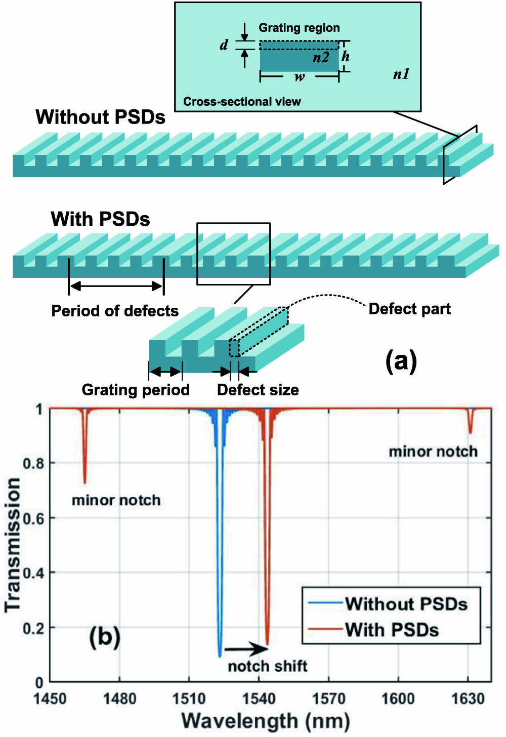
    Fig. 1. (a) Schematic and (b) transmission spectra of the uniform Bragg grating with PSDs and without PSDs.
    2D transmission spectra when the relative defect size is changed from −0.5 to 0.5.
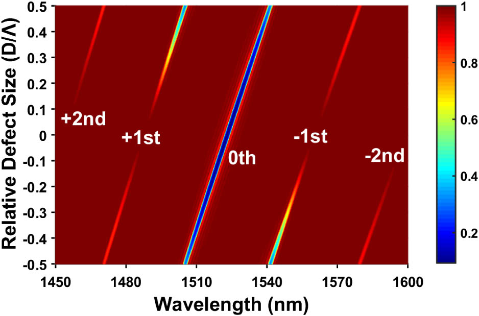
    Fig. 2. 2D transmission spectra when the relative defect size is changed from 0.5 to 0.5.
    2D transmission spectra when the period of defects is changed from 1.0 to 10 μm.
    Fig. 3. 2D transmission spectra when the period of defects is changed from 1.0 to 10 μm.
    (a) Bragg wavelengths of 0 and ±1-order subgratings and (b) the RGS of each order subgrating versus the relative defect size.
    Fig. 4. (a) Bragg wavelengths of 0 and ±1-order subgratings and (b) the RGS of each order subgrating versus the relative defect size.
    Comparison of the actual fabrication patterns utilized in an eight-wavelength grating array without PSDs and with PSDs.
    Fig. 5. Comparison of the actual fabrication patterns utilized in an eight-wavelength grating array without PSDs and with PSDs.
    (a) Transmission spectra of the PSD-based eight-wavelength π-phase-shifted Bragg grating array whose parameters are given in Table 2, and (b) the influence of the DSE.
    Fig. 6. (a) Transmission spectra of the PSD-based eight-wavelength π-phase-shifted Bragg grating array whose parameters are given in Table 2, and (b) the influence of the DSE.
    RGS versus occupation ratio of the grating-stitched method. A schematic of a sample unit of the stitched grating is shown in the inset.
    Fig. 7. RGS versus occupation ratio of the grating-stitched method. A schematic of a sample unit of the stitched grating is shown in the inset.
    Lasing spectrum, power [inset (I)], and gain [inset (II)] distribution along the cavity of DFB lasers with PSDs and without PSDs.
    Fig. 8. Lasing spectrum, power [inset (I)], and gain [inset (II)] distribution along the cavity of DFB lasers with PSDs and without PSDs.
    Parameter (Symbol)Value
    Waveguide width (w)1 μm
    Waveguide height (h)0.4 μm
    Grating depth (d)10 nm
    Total length (L)300 μm
    Grating period (Λ)238 nm
    Filling factor (r)0.5
    Waveguide refractive index (n2)3.4
    Cladding refractive index (n1)3.1
    Defect size (D)59.5 nm
    Period of defects (P)4.5 μm
    Table 1. Parameters in TMM Calculation
    Period of Defects (μm)Bragg Wavelength (nm)Equivalent Grating Period (nm)
    7.7401535.0239.84
    7.2521535.8239.97
    6.8231536.6240.09
    6.4421537.4240.22
    6.1021538.2240.34
    5.7961539.0240.47
    5.5191539.8240.59
    5.2681540.6240.72
    Table 2. Periods of Defects for Eight-Wavelength π-Phase-Shifted Bragg Grating Array
    Parameter (Symbol)Value
    Cavity length (L)400 μm
    Grating period without PSDs (Λ)241 nm
    Grating period with PSDs (Λ0)238 nm
    Defect size (D)59.5 nm
    Period of defects (P)4.78 μm
    Active layer width (w)1.5 μm
    Active layer thickness (d)0.12 μm
    Optical confinement factor (Γ)0.3
    Effective refractive index3.2
    at bias current (neff)
    Group refractive index (ng)3.7
    Refractive index modulation (Δn0)0.003
    Filling factor (r)0.5
    Internal loss (α)4×10³  m1
    Spontaneous emission rate (τ1)2.5×10¹⁰  s1
    Bimolecular recombination1×1016  m3s1
    coefficient (B)
    Auger recombination coefficient (C)3×1041  m6s1
    Transparent carrier density (N0)1.2×1024  m3
    Linear gain coefficient (a)2.7×10²⁰  m2
    Linewidth enhancement factor (βC)1.5
    Bias current (IB)20 mA
    Table 3. Modeling Laser Parameters
    Rulei Xiao, Yuechun Shi, Renjia Guo, Ting Chen, Lijun Hao, Xiangfei Chen. Periodic structural defects in Bragg gratings and their application in multiwavelength devices[J]. Photonics Research, 2016, 4(2): 0035
    Download Citation