
Jinlai Cui, Jun Zheng, Yupeng Zhu, Xiangquan Liu, Yiyang Wu, Qinxing Huang, Yazhou Yang, Zhipeng Liu, Zhi Liu, Yuhua Zuo, Buwen Cheng, "High-speed GeSn resonance cavity enhanced photodetectors for a 50 Gbps Si-based 2 μm band communication system," Photonics Res. 12, 767 (2024)
- Photonics Research
- Vol. 12, Issue 4, 767 (2024)
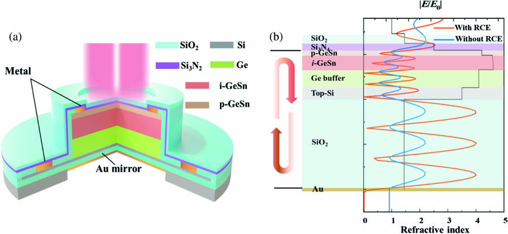
Fig. 1. (a) Schematic diagram of the 2 μm RCE-PD; (b) according to the finite difference-time domain (FDTD) method, the simulation of the normalized electric field intensity | E / E 0 |

Fig. 2. High resolution 2 θ - ω
Fig. 3. (a) I-V curves of the GeSn photodetector with a diameter of 20 μm: dark, photocurrent under 2 μm laser incidence with or without RCE structure. The incident light power was 1 mW. The inset shows responsivities of the photodetector with RCE structure under 0 V bias and − 2 V
Fig. 4. (a) Normalized frequency responses of PDs with various mesa diameters at 2 μm incident light with − 4 V
Fig. 5. Comparison of 3-dB bandwidth of high-speed photodetectors at 2 μm band in different groups.
Fig. 6. (a) Demonstration link diagram of 2 μm communication system, consisting of 2 μm laser, polarization controller, Si carrier-depletion Mach–Zehnder modulator, bias-T, etc. Black and red lines represent the optical and electrical connections, respectively. (b) Eye diagrams of 20 Gbps, 30 Gbps, 40 Gbps, 50 Gbps GeSn photodetectors with a diameter of 8 μm at − 4 V
|
Table 1. Comparison of 3-dB Bandwidth and Responsivity of High-Speed Photodetectors at 2 μm Wavelength in Different Material Groups


Set citation alerts for the article
Please enter your email address

© Copyright 2018-2021 | Chinese Laser Press. All Rights Reserved 沪ICP备15018463号-20