
Carlo Gigli, Giuseppe Leo. All-dielectric χ(2) metasurfaces: recent progress[J]. Opto-Electronic Advances, 2022, 5(7): 210093
- Opto-Electronic Advances
- Vol. 5, Issue 7, 210093 (2022)
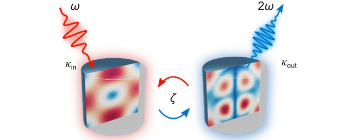
Fig. 1. Simplified scheme of SHG in a leaky cavity. FF (SH) beam is represented in red (blue), κin (κout) denotes the input (output) coupling coefficient and
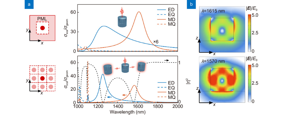
Fig. 2. Comparison between isolated (top) and arrayed (bottom) air-suspended GaAs nanoantennas with radius r = 200 nm and height h=400 nm. A normally impinging beam is linearly polarized along x, and the array (bottom) has a period of p=1 μm. (a ) Scattering cross section decomposed in electric (blue) and magnetic (red) multipolar contributions, computed by projecting the field inside a nanoparticle onto vector spherical harmonics95. The scattering cross section from the isolated particle has been scaled by a factor 6 to be compared with the plot on the bottom. The black dashed curve (bottom) displays the array transmission. (b ) Near-field enhancement corresponding to the magnetic-dipole resonance.
Fig. 3. Arrays of quasi-independent dielectric χ(2) Mie-type resonators. (a ) SHG from a GaAs metasurface radiated into different diffraction orders vs. pump polarization angle. Green: total; blue: (0,±1) orders; red: (±1,0) orders; black: (0,0) order98. (b ) SH back-focal plane (BFP) imaging of a LiNbO3 metasurface for horizontally (center) or vertically (right) polarized pump101. (c ) Mechanism to partially redirect SHG from an AlGaAs metasurface close to normal direction99. (d ) Controlling SH polarization. BFP imaging of SH from isolated (left) or arrayed (right) AlGaAs nanoantennas with elliptical basis100. (e ) Broadband frequency generation in a GaAs metasurface through multiple nonlinear processes96.
Fig. 4. Nonlinear wavefront shaping in dielectric metasurfaces. (a ) Si metasurface implementing the first Kerker condition and funneling THG into the (-1)-diffraction order106. (b ) Top: TH focusing from a Si metasurface. Bottom: Nonlinear imaging and spatial correlation for two apertures107. (c ) SH beam-steering (left) and focusing (right) from an AlGaAs metasurface108. (d ) SH geometric phase control in a Si metasurface109.
Fig. 5. Quasi-BIC mode generation in nonlinear metasurfaces. A few ways to break the symmetry and reveal the high-Q resonance are sketched in the top row. Yellow (blue) color denotes a material addition (removal). (a ) L-shaped GaAs/AlGaO heterostructures124. (b ) Asymmetric Si nanodimers made of two rods with different widths125. (c ) T-shaped Si resonators126. (d ) Asymmetric GaP nanodimers made of two elliptical-basis cylinders rotated by an angle θ127.
Fig. 6. SHG efficiency vs. Q-factor of the dominant FF mode for different resonant devices (markers’ color) and materials (markers’ shape).
|
Table 1. Most common materials for χ(2) nonlinear nano-optics. Refractive index n and second-order nonlinear coefficient d all refer to a wavelength λ = 1550 nm but for LiNbO3 for which we consider λ = 1313 nm.

Set citation alerts for the article
Please enter your email address
© Copyright 2018-2021 | Chinese Laser Press. All Rights Reserved 沪ICP备15018463号-20