
Jinyu Cao, Shuhui Li, Yajun Tong, Ming Tang, Wenbin Li, Qiushi Huang, Huaidong Jiang, Zhanshan Wang. Damage resistance of B4C reflective mirror irradiated by X-ray free-electron laser[J]. Chinese Optics Letters, 2023, 21(2): 023401
- Chinese Optics Letters
- Vol. 21, Issue 2, 023401 (2023)
Abstract
1. Introduction
With the special characteristics of high peak brightness and ultrashort pulse width, the X-ray free-electron laser (XFEL) is able to induce complicated dynamic processes when interacting with materials[1–6]. For the X-ray reflective optics used at XFEL beamlines, this interaction process can easily destroy or deteriorate these optical mirrors, thereby reducing the XFEL quality and affecting applications in user experiments. In recent years, various XFEL-induced damage mechanisms have been found, such as thermal melting[7–11], ablation[12], thermal stress[8], thermal and nonthermal phase transition[13,14]. In-depth study of XFEL-induced damage process of optical film mirrors, analysis of film damage mechanisms, and preparation of X-ray mirrors with high damage resistance are of great significance.
Generally, when designing XFEL beamlines, the damage threshold of a reflective mirror can be roughly estimated by[15–17]
Here, is the melting dose per atom, , , , , , , and represent the density, the Avogadro constant, the Boltzmann constant, the energy deposition depth, the atomic weight, the reflectivity, and the grazing incidence angle, respectively.
Sign up for Chinese Optics Letters TOC. Get the latest issue of Chinese Optics Letters delivered right to you!Sign up now
The relationship between the damage threshold and the melting dose has been tested by free-electron laser damage experiments in the photon energy range from extreme ultraviolet (EUV) to X-ray[7–12]. Under the normal incidence condition, it was found that the measured threshold doses for , SiC are generally in agreement with the calculated melting dose in EUV range of 13.5–21.7 nm[7]. At X-ray photon energy of 0.83 and 10 keV, it was also demonstrated that the measured threshold doses for optical materials of , Si, , Pt, and Rh are quite consistent with the theoretical values[8,12]. However, at the grazing incidence condition[9–11], the experimental damage thresholds are much higher than the calculated ones based on Eq. (1), where the electron collision escape, scattering, and other secondary processes are not easily taken into account. For simulating FEL-induced thermal and non-thermal phase transition processes, Ziaja et al.[18,19] have developed an effective hybrid model combining tight binding molecular dynamics with Monte Carlo simulation and Boltzmann collision integrals for nonadiabatic electron–ion coupling. Since this hybrid model combines a variety of complicated theoretical calculations, it is obviously a time-consuming work to estimate the damage resistances of X-ray reflective mirrors with different film materials.
Presently, China is building Shanghai HIgh repetitioN rate XFEL and Extreme light facility (SHINE), which is designed to cover the photon energy range of 0.4–25 keV[20,21]. is likely to be chosen as the main coating material for reflective mirrors at SHINE because of its excellent characteristics of high hardness, high melting point, and optical performance. So, it is important to develop a relatively simple and convenient method to evaluate the damage resistance of mirrors at the working photon energy range for safety applications. In this paper, a simple theoretical model is provided to calculate the damage thresholds of mirrors based on the Monte Carlo simulation and the enthalpy method. Considering that the damage resistances are related to the film structure, the photon energy, and the grazing incidence angle, the effects of the film thickness on damage thresholds for mirror are analyzed, and the damage thresholds in the photon energy range of 0.4–25 keV are given and discussed at a typical grazing incidence angle of 2 mrad. It is found, unexpectedly, that the photon energy-dependent damage resistance is related not only with the film but also with the Si substrate.
2. Theoretical Model
When materials are irradiated by ultrashort femtosecond XFEL, the evolution processes of electronic excitation and relaxation will be involved. Through photoabsorption, X-ray photons interact primarily with inner-shell electrons to emit photoelectrons with high kinetic energy. Then the cascaded relaxation processes, such as the fluorescence and Auger decay as well as electron impact ionization, will be followed to exchange energy among electrons. The time scale for this electronic thermalization is about several hundred femtoseconds[11,22,23]. Through this ultrafast process, the electrons are at a high temperature, while the crystal lattices are still at a low temperature. The thermalization process between electrons and lattices takes a longer time— about picoseconds—until reaching thermal equilibrium. Finally, the heat energy is transferred inside the material through thermal conduction. In this model, the photoabsorption and the relaxation processes, as well as the heat transfer, are considered, where the thermalization between electrons and lattices is assumed to be transient for XFEL interaction with mirrors. The Monte Carlo method is adopted to simulate X-ray photoabsorption and the cascading processes. The enthalpy method is used to simulate the heat transfer process.
2.1. Monte Carlo simulation of X-ray interaction with mirrors
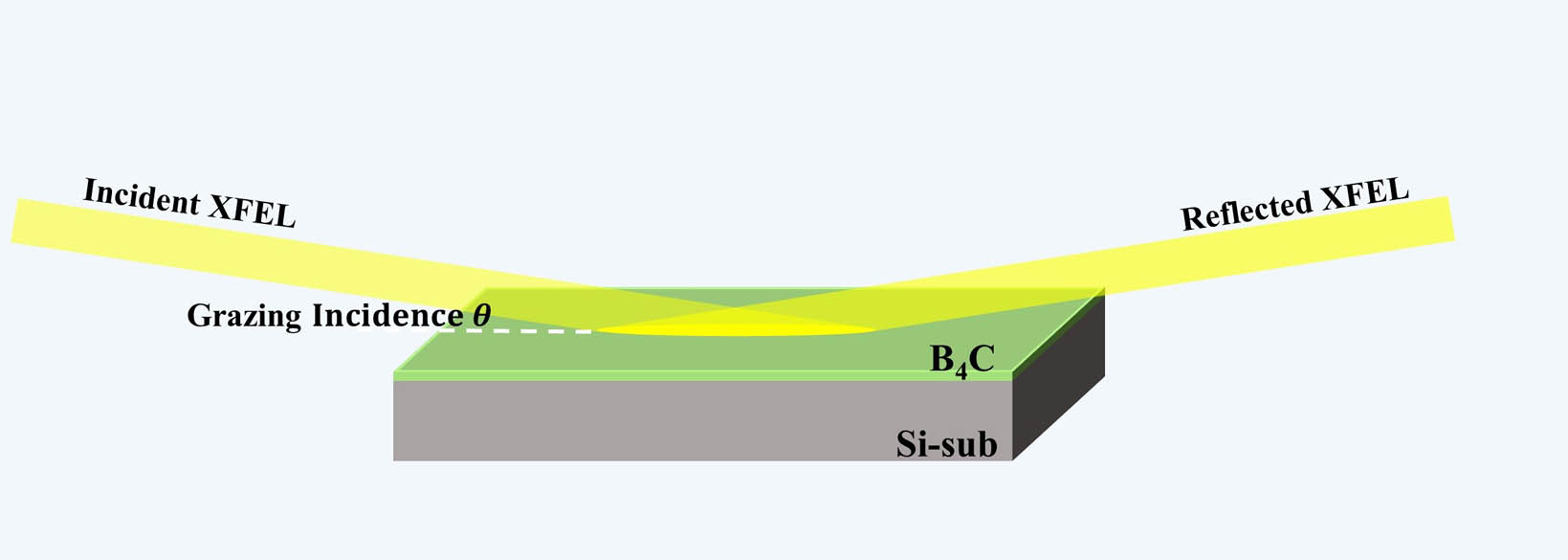
Figure 1 gives a schematic of an XFEL beam incident on a mirror under grazing incidence. When the total reflection is fulfilled, most part of the incident photon energy will be reflected due to the high reflectivity . The absorbed energy by the mirror is only a few parts of the incident energy. The X-ray penetration depth inside the film medium is quite shallow, which is about several nanometers. However, the energetic photo- and secondary electrons generated in the X-ray interaction volume can escape from the mirror surface or travel deeply into the film or even into the substrate, which dramatically affects the energy deposition range.
![]()
Figure 1.Schematic of an XFEL beam incident on a B4C/Si-sub mirror under grazing incidence.
In this study, X-ray energy deposited along the depth direction was simulated using Geant4 Monte Carlo simulation code[24], where the photoionization, Auger and fluorescence effects, and electron elastic and inelastic scattering processes were taken into account. Here the absorbed energy fraction represents the ratio of deposited energy per unit depth to the absorbed energy . Figure 2 gives for X-ray interaction with mirror at 1 keV and 12 keV with the grazing incidence angle of . For comparison, the theoretical results of considering only the exponential decay of the X-ray into the mirror are also calculated by[25]
![]()
Figure 2.Absorbed energy fractions along the depth direction for B4C(50 nm)/Si-sub irradiated by XFEL at 1 keV and 12 keV with the grazing incidence angle of 2 mrad.
Here the X-ray attenuation length can be calculated by
At 1 keV, according to Eq. (2), most part of the absorbed energy () should be localized in the surface layer of film, since the X-ray penetration depth is only 3.07 nm at the grazing angle of 2 mrad. However, the Monte Carlo simulation shows that of the absorbed energy is released and escaped from the surface by photo- and Auger electrons as well as X-ray fluorescence. Only of the absorbed energy is deposited into the film with the penetration depth about 30 nm, while the Si substrate absorbs almost nothing. At 12 keV, the simulation shows that 25.9% of the total absorbed energy is released from the mirror surface, and the remaining energy is deposited deeply into the mirror. Contrary to the case at 1 keV, the film is deposited at only 2.9% of the absorbed energy at 12 keV, while the Si substrate absorbs the most, to the deposition depth of . Due to the transport by the energetic electrons, the deposition depth is dramatically increased, which is quite beneficial to enhance the damage resistance of X-ray mirrors, especially under the grazing incidence condition.
2.2. Enthalpy method
Materials irradiated by XFEL may undergo phase changes after absorbing enough energy in a short time. The methods for solving the phase transition process mainly include the equivalent heat capacity method and the enthalpy method[26,27]. The enthalpy method uses enthalpy as the dependent variable to solve the heat transfer differential equation. In this study, the enthalpy method was used to simulate the accumulation and the transport of heat with a simple one-dimensional thermal diffusion model as represented by
Here, is the enthalpy of the material with units of , is the heat source term with units of [], and represents the depth direction. is the thermal conductivity expressed in [W/(m·K)] and is the thermal capacity expressed in []. For and Si, the thermal conductivity and the thermal capacity as a function of temperature are provided in Refs. [28–30]. Here, a one-dimensional thermal diffusion model was considered because the projected area of the XFEL beam on the mirror is much larger than the depth of the heat-affected zone under the grazing incidence condition. For this calculation, the initial enthalpy value was assumed as , which corresponds to an initial temperature of 298.15 K. The film surface was assumed to be adiabatic, and the sample bottom was kept at room temperature. The time- and depth-dependent heat source is expressed as
3. Results and Discussion
3.1. Damage mechanisms of B4C (50 nm)/Si-sub
The time-dependent depth distribution of enthalpy is shown in Fig. 3 for mirror irradiated under the grazing incidence angle of 2 mrad by XFEL at the fluences of at 1 keV and at 12 keV. These two particular fluences are chosen here, since the fluences of at 1 keV and at 12 keV are considered as the damage thresholds for mirror, as explained below. The reflectivities used in this simulation were determined by IMD software to be 0.991 and 0.999 at photon energies of 1 keV and 12 keV, respectively. The surface roughness of film was set as 0.3 nm, and the interface roughness of was set as 0.2 nm.
![]()
Figure 3.Time-dependent depth distribution of enthalpy for B4C(50 nm)/Si-sub irradiated by XFEL at the fluence of (a) 1250 J/cm2 at 1 keV and (b) 2.4 × 10⁵ J/cm2 at 12 keV. The grazing incidence angle is 2 mrad in both cases. The interface between B4C and Si-sub is marked by dashed gray lines, and the damage boundary is marked by solid white curves.
According to the NIST website[30], the enthalpy levels of and correspond to the melting temperature of and Si, respectively. At 1 keV in Fig. 3(a), the maximum enthalpy of is achieved on the surface of film at the fluence of , while the maximum enthalpy of the Si substrate is still lower than . It means the surface of film just reaches the melting point, but the temperature of the Si substrate is still lower than its melting point. So, the damage should occur on the top surface of film at 1 keV, with the damage threshold of . At 12 keV in Fig. 3(b), the Si surface layer with a depth of about 1 µm has higher enthalpy than film, since more energy is deposited on Si-sub than on . At the fluence of , the melting damage occurs in Si-sub at below the interface. From the simulations, it can be found that there are two different damage mechanisms for mirror, depending on the incident photon energy, where one is caused by the melting of film surface and the other one is caused by the melting of Si-sub near the interface. The simulation result at 12 keV is quite consistent with the experimental observation by Aquila et al.[10] that the damage occurred at the interface for at the grazing incidence angle of 2 mrad. The experimental damage threshold for the mirror at 12 keV was also given as , which is different from our result because of the different reflectivity used. In this study, the theoretical reflectivity was calculated using the density of bulk material, which leads to a higher reflectivity, since the bulk material is usually denser than the film. If the reflectivity of 0.975 given by Aquila et al.[10] is adopted in our simulation, the damage threshold of is obtained, which is close to the experimental result. Obviously, the actual reflectance has a great influence on the damage resistance of mirrors. Thus, it is quite important to calibrate the reflectivity accurately before using the reflective mirrors at the XFEL beamlines.
3.2. Correlation between
The film thickness of the reflective mirror has strong effects on the damage resistance[31,32]. However, no one has discussed this important question about a reflective mirror being used at XFEL beamlines. In order to answer this question, we explored the damage resistance as a function of film thickness at the photon energy of 12 keV and the grazing incidence angle of 2 mrad. Figure 4 gives the simulated for with the film thickness ranging from 10 to 200 nm. It can be seen that all the energy deposited per unit depth shows a slight upward trend along the depth direction in , while it decreases gradually with a deposition depth about 1 µm in the Si substrate. As the film thickness increases from 10 to 200 nm, the ratio of the escape energy to the absorbed energy decreases from 27.5% to 20.4%, and most of the absorbed energy is still deposited in the Si substrate. Therefore, the melting damage on the surface of the Si-sub is still the main damage mechanism at 12 keV for mirrors with different film thicknesses.
![]()
Figure 4.Absorbed energy fraction for B4C/Si-sub mirror with different B4C film thicknesses at the photon energy of 12 keV and the grazing incidence angle of 2 mrad.
Using this model, the damage thresholds for mirrors with different film thicknesses are calculated as given in Fig. 5. As the film thickness increases from 10 to 50 nm, the damage threshold increases from to , which is mainly due to the reflectivity increasing from 0.996 to 0.999. For the film thickness above 50 nm, the damage thresholds remain almost at a constant value of , where the optimal damage resistance is achieved. Considering the laser resistance and the optical performance, the typical film thickness of 50 nm is still recommended for a reflective mirror in practical applications.
![]()
Figure 5.Damage thresholds of B4C mirrors with different B4C film thicknesses (solid black squares) at 12 keV and the grazing angle of 2 mrad; reflectivity of B4C mirrors as a function of film thickness calculated with IMD software (blue line).
3.3. FEL damage resistance of
Figure 6 gives the damage thresholds of a mirror irradiated by XFEL in the energy range of 0.4–25 keV at the grazing incidence angle of 2 mrad. These damage thresholds were determined according to the theoretical reflectivity, as shown by the solid red line.
![]()
Figure 6.Damage threshold of the B4C(50 nm)/Si-sub mirror at different X-ray energies (solid blue squares). The theoretical reflectivity was calculated using IMD software (solid red line). The absorption K-edge of Si at 1.839 keV is indicated by a green dashed line.
When X-ray energy increases from 0.4 to 1.8 keV, the damage threshold increases sharply from to , where the damage occurs at the surface of the film similar to the case at 1 keV as given in Fig. 3(a). At 1.839 keV, which corresponds to the Si K-edge, there is a sharp drop for the damage threshold due to the enhanced photoabsorption by the Si substrate. From 1.9 to 12 keV, the damage threshold increases gradually from to , where the damage occurs in the surface layer of Si-sub near the interface, which is similar to the case at 12 keV, as shown in Fig. 3(b). Additionally, with the increase of photon energy, the photoelectron kinetic energy increases, which makes the deposition depth deeper. So, the increase of the damage threshold from 1.9 to 12 keV is mainly due to the deeper deposition depth inside the Si. From 12 to 15 keV, the slight drop in damage threshold is due to a slight decrease of reflectivity. For photon energy above 15 keV, the damage threshold of mirror drops sharply, which is caused by the low reflectivity. From the simulation, it is demonstrated that the energy range around the Si K-edge at 1.839 keV should be avoided for safety reasons when applying the mirror at XFEL beamlines. Additionally, the working angle for the mirror should be less than 2 mrad when applying it at a photon energy range above 15 keV.
4. Conclusion
In this study, a simple model based on Monte Carlo simulation and the enthalpy method is proposed to evaluate the damage resistance of reflective mirrors irradiated by XFEL at a typical grazing incidence angle of 2 mrad. It is found that two different mechanisms are responsible for XFEL damage of mirrors. In the photon energy range of 0.4–1.8 keV, the melting damage happens on the surface layer of film because the absorbed energy is mainly deposited inside the film. At the photon energy above 1.9 keV, the melting damage occurs in the surface layer of the Si substrate close to the interface because the absorbed energy is deposited deeply into the Si substrate by the transport of the energetic electrons. For mirror with an optimum film thickness of 50 nm, the damage thresholds are determined in the photon energy range of 0.4–25 keV using the theoretical reflectivity. According to the simulations, it is suggested that the energy range around the Si K-edge should be avoided for safety reasons when using a mirror at XFEL beamlines. It is expected this research will be helpful for the design and operation of reflective mirrors at XFEL beamlines.
References
[1] S. P. Hau-Riege, A. Graf, T. Döppner, R. A. London, J. Krzywinski, C. Fortmann, S. H. Glenzer, M. Frank, K. Sokolowski-Tinten, M. Messerschmidt, C. Bostedt, S. Schorb, J. A. Bradley, A. Lutman, D. Rolles, A. Rudenko, B. Rudek. Ultrafast transitions from solid to liquid and plasma states of graphite induced by X-ray free-electron laser pulses. Phys. Rev. Lett., 108, 217402(2012).
[2] B. Rudek, S.-K. Son, L. Foucar. Ultra-efficient ionization of heavy atoms by intense X-ray free-electron laser pulses. Nat. Photonics, 6, 858(2012).
[3] Z. Jurek, G. Faigel, M. Tegze. Dynamics in a cluster under the influence of intense femtosecond hard X-ray pulses. Eur. Phys. J. D, 29, 217(2004).
[4] M. Bergh, N. Tmneanu, S. P. Hau-Riege, H. A. Scott. Interaction of ultrashort X-ray pulses with B4C, SiC and Si. Phys. Rev. E, 77, 026404(2008).
[5] K. Nass. Radiation damage in protein crystallography at X-ray free-electron lasers. Acta Cryst. D, 75, 211(2019).
[6] R. Soufli, S. L. Baker, J. C. Robinson, E. M. Gullikson, T. J. McCarville, M. J. Pivovaroff, P. Stefan, S. P. Hau-Riege, R. Bionta. Morphology, microstructure, stress and damage properties of thin film coatings for the LCLS X-ray mirrors. Proc. SPIE, 7361, 73610U(2009).
[7] S. P. Hau-Riege, R. A. London, R. M. Bionta. Wavelength dependence of the damage threshold of inorganic materials under extreme-ultraviolet free-electron-laser irradiation. Appl. Phys. Lett., 95, 111104(2009).
[8] S. P. Hau-Riege, R. A. London, A. Graf, S. L. Baker, R. Soufli, R. Sobierajski, T. Burian, J. Chalupský, L. Juha, J. Gaudin, J. Krzywinski, L. Juha, J. Gaudin, J. Krzywinski, S. Moeller, M. Messerschmidt, J. D. Bozek, C. Bostedt. Interaction of short X-ray pulses with low-Z X-ray optics materials at the LCLS free-electron laser. Opt. Express, 18, 23933(2010).
[9] T. Koyama, H. Yumoto, T. Miura, K. Tono, T. Togashi, Y. Inubushi, T. Katayama, J. Kim, S. Matsuyama, M. Yabashi, K. Yamauchi, H. Ohashi. Damage threshold of coating materials on x-ray mirror for x-ray free electron laser. Rev. Sci. Instrum., 87, 051801(2016).
[10] A. Aquila, R. Sobierajski, C. Ozkan, V. Hájková, T. Burian, J. Chalupský, L. Juha, M. Störmer, S. Bajt, M. T. Klepka, P. Dłużewski, K. Morawiec, H. Ohashi, T. Koyama, K. Tono, Y. Inubushi, M. Yabashi, H. Sinn, T. Tschentscher, A. P. Mancuso, J. Gaudin. Fluence thresholds for grazing incidence hard x-ray mirrors. Appl. Phys. Lett., 106, 241905(2015).
[11] I. Milov, I. A. Makhotkin, R. Sobierajski, N. Medvedev, V. Lipp, J. Chalupský, J. M. Sturm, K. Tiedtke, G. De Vries, M. Störmer, F. Siewert, R. Van De Kruijs, E. Louis, I. Jacyna, M. Jurek, L. Juha, V. Hájková, V. Vozda, T. Burian, K. Saksl, B. Faatz, B. Keitel, E. Plönjes, S. Schreiber, S. Toleikis, R. Loch, M. Hermann, S. Strobel, H.-K. Nienhuys, G. Gwal. Mechanism of single-shot damage of Ru thin films irradiated by femtosecond extreme UV free-electron laser. Opt. Express, 26, 19665(2018).
[12] T. Koyama, H. Yumoto, K. Tono, T. Sato, T. Togashi, Y. Inubushi, T. Katayama, J. Kim, S. Matsuyama, H. Mimura, M. Yabashi, K. Yamauchi, H. Ohashi. Damage threshold investigation using grazing incidence irradiation by hard X-ray free electron laser. Proc. SPIE, 8848, 88480T(2013).
[13] J. Chalupský, V. Hájková, V. Altapova, T. Burian, A. J. Gleeson, L. Juha, M. Jurek, H. Sinn, M. Störmer, R. Sobierajski, K. Tiedtke, S. Toleikis, Th. Tschentscher, L. Vyšín, H. Wabnitz, J. Gaudin. Damage of amorphous carbon induced by soft x-ray femtosecond pulses above and below the critical angle. Appl. Phys. Lett., 95, 031111(2009).
[14] I. Inoue, Y. Deguchi, B. Ziaja, T. Osaka, M. M. Abdullah, Z. Jurek, N. Medvedev, V. Tkachenko, Y. Inubushi, H. Kasai, K. Tamasaku, T. Hara, E. Nishibori, M. Yabashi. Atomic-scale visualization of ultrafast bond breaking in X-ray-excited diamond. Phys. Rev. Lett., 126, 117403(2021).
[15] H. Sinn, J. Gaudin, L. Samoylova, A. Trapp, G. Galasso. Conceptual design report: X-ray optics and beam transport(2011).
[16] R. A. London, R. A. Bionta, R. O. Tatchyn, S. Roesler. Computational simulations of high intensity X-Ray interaction. Proc. SPIE, 4500, 51(2001).
[17] M. Yabashi, A. Higashiya, K. Tamasaku, H. Kimura, T. Kudo, H. Ohashi, S. Takahashi, S. Goto, T. Ishikawa. Optics development for Japanese XFEL project. Proc. SPIE, 6586, 658605(2007).
[18] N. Medvedev, V. Tkachenko, B. Ziaja. Modeling of nonthermal solid-to-solid phase transition in diamond irradiated with femtosecond x-ray FEL pulse. Contrib. Plasm. Phys., 55, 12(2015).
[19] Z. Jurek, B. Ziaja, R. Santra. Applicability of the classical molecular dynamics method to study x-ray irradiated molecular systems. J. Phys. B, 47, 124036(2014).
[20] K. Li, H. X. Deng. Systematic design and three-dimensional simulation of X-ray FEL oscillator for Shanghai coherent light facility. Nucl. Instrum. Methods Phys. Res., 895, 40(2018).
[21] H. H. Lv, Y. B. Leng, Y. B. Yan, H. Y. Wang. The high level application architecture of the control system for SHINE. Nucl. Instrum. Methods Phys. Res., 908, 167(2018).
[22] T.-H. Dinh, N. Medvedev, M. Ishino, T. Kitamura, N. Hasegawa, T. Otobe, T. Higashiguchi, K. Sakaue, M. Washio, T. Hatano, A. Kon, Y. Kubota, Y. Inubushi, S. Owada, T. Shibuya, B. Ziaja, M. Nishikino. Controlled strong excitation of silicon as a step towards processing materials at sub-nanometer precision. Commun. Phys., 2, 150(2019).
[23] I. Milov, V. Zhakhovsky, D. Ilnitsky, K. Migdal, V. Khokhlov, Y. Petrov, N. Inogamov, V. Lipp, N. Medvedev, B. Ziaja, V. Medvedev, I. A. Makhotkin, E. Louis, F. Bijkerk. Two-level ablation and damage morphology of Ru films under femtosecond extreme UV irradiation. Appl. Surf. Sci., 528, 146952(2020).
[24] S. Agostinelli, J. Allison, D. Zschiesche. Geant4–a simulation toolkit. Nucl. Instrum. Methods A, 506, 250(2003).
[25] B. L. Henke, E. M. Gullikson, J. C. Davis. X-ray interactions: photoabsorption, scattering, transmission, and reflection at E = 50–30000 eV, Z = 1–92. Atom. Data Nucl. Data Tabl., 54, 181(1993).
[26] H. Hu, S. A. Argyropoulos. Mathematical modelling of solidification and melting: a review. Modelling Simul. Mater. Sci. Eng., 4, 371(1996).
[27] R. Sobieraski, I. Jacyna, P. Dłużewski, M. T. Klepka, D. Klinger, J. B. Pełka, T. Burian, V. Hájková, L. Juha, K. Saksl, V. Vozda, I. Makhotkin, E. Louis, B. Faatz, K. Tiedtke, S. Toleikis, H. Enkisch, M. Hermann, S. Strobel, R. A. Loch, J. Chalupsky. Role of heat accumulation in the multi-shot damage of silicon irradiated with femtosecond XUV pulses at a 1 MHz repetition rate. Opt. Express, 24, 15468(2016).
[28] H. R. Shanks, P. D. Maycock, P. H. Sidles, G. C. Danielson. Thermal conductivity of silicon from 300 to 1400 K. Phys. Rev., 130, 1743(1963).
[29] H. O. Pierson. Handbook of Refractory Carbides and Nitrides(1996).
[30] . NIST Chemistry WebBook.
[31] E. Matthias, M. Reichling, J. Siegel, O. W. Käding, S. Petzoldt, H. Skurk, P. Bizenberger, E. Neske. The influence of thermal diffusion on laser ablation of metal films. Appl. Phys. A, 58, 129(1994).
[32] F. Barkusky, A. Bayer, S. Döring, P. Grossmann, K. Mann. Damage threshold measurements on EUV optics using focused radiation from a table-top laser produced plasma source. Opt. Express, 18, 4346(2010).

Set citation alerts for the article
Please enter your email address
© Copyright 2018-2021 | Chinese Laser Press. All Rights Reserved 沪ICP备15018463号-20