• Chinese Optics Letters
  • Vol. 22, Issue 3, 031302 (2024)
Hongjie Guo1、2, Haifeng Liu1、3、*, Ming Lei4, Manqing Tan1, and Zhigang Song1
Author Affiliations
  • 1Institute of Semiconductors, Chinese Academy of Sciences, Beijing 100083, China
  • 2College of Materials Science and Opto-electronics Technology, University of Chinese Academy of Sciences, Beijing 100049, China
  • 3Beijing Huairou Instruments and Sensors Co., Ltd., Beijing 101400, China
  • 4Beijing Institute of Automation and Control Equipment, Key Laboratory of National Defense Science and Technology of Inertial Technology, Beijing 100074, China
  • show less
    DOI: 10.3788/COL202422.031302 Cite this Article Set citation alerts
    Hongjie Guo, Haifeng Liu, Ming Lei, Manqing Tan, Zhigang Song. Research progress of integrated optical gyroscope[J]. Chinese Optics Letters, 2024, 22(3): 031302 Copy Citation Text show less
    Configuration of interferometric optical gyroscopes.
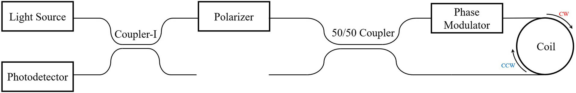
    Fig. 1. Configuration of interferometric optical gyroscopes.
    (a) IIOGs based on the silica platform from Shang et al.[9]. (b) IIOGs based on the silica platform from Wang et al.[8]. (c) IIOGs based on the silicon platform from Tran et al.[12].
    Fig. 2. (a) IIOGs based on the silica platform from Shang et al.[9]. (b) IIOGs based on the silica platform from Wang et al.[8]. (c) IIOGs based on the silicon platform from Tran et al.[12].
    (a) Schematic diagram of the MIOC[16]. (b) Optimized block structure for the MIOC to improve the PER[16]. (c) Schematic diagram of a mixed-signal MIOC[15].
    Fig. 3. (a) Schematic diagram of the MIOC[16]. (b) Optimized block structure for the MIOC to improve the PER[16]. (c) Schematic diagram of a mixed-signal MIOC[15].
    Schematic diagram of the integrated waveguide coils. (a) SOI[21], (b) SiO2[22], (c) SiN[23].
    Fig. 4. Schematic diagram of the integrated waveguide coils. (a) SOI[21], (b) SiO2[22], (c) SiN[23].
    Schematic diagram of the resonant microcavity platform. (a) SiO2[26], (b) SiN[31], (c) polymer[34], (d) LRSPP[35], (e) CaF2[38], and (f) InP[36].
    Fig. 5. Schematic diagram of the resonant microcavity platform. (a) SiO2[26], (b) SiN[31], (c) polymer[34], (d) LRSPP[35], (e) CaF2[38], and (f) InP[36].
    Schematic diagram of CROW[46].
    Fig. 6. Schematic diagram of CROW[46].
    (a) Schematic diagram of IROGs based on exceptional points[59]. (b) Schematic diagram of IROGs based on exceptional surfaces[63].
    Fig. 7. (a) Schematic diagram of IROGs based on exceptional points[59]. (b) Schematic diagram of IROGs based on exceptional surfaces[63].
    PlatformInsertion LossLengthFootprintARWBias Drift
    SOI[21]29 mm0.42 mm251.3 deg/h
    SiO2[22]8.37 dB2.14 m121 cm21.26deg/h7.32 deg/h
    SiN[23]16.2 dB3 m12.57 cm28.52deg/h58.7 deg/h
    Table 1. Performance of the Integrated Coil Waveguides
    MaterialYearResearch TeamDiameter (cm)Q (106)Loss
    SiO2[30]2017Zhejiang University2.514.6
    SiO2[26]2013NIST0.28290
    SIN[31]2022Beihang University3.515.41.2 dB/m
    SIN[32]2021Beihang University1.62.64 dB/m
    Polymer[34]2022Southeast University210.118 dB/cm
    LRSPP[35]2014Southeast University40.14 dB/cm
    InP[36]2013Politecnico di Bari2.60.970.45 dB/cm
    CaF2[37]2007California Institute of Technology100,000
    CaF2[38]2017Eowaves0.7> 100
    SOI[39]2012Massachusetts Institute of Technology0.492202.7 dB/m
    Table 2. Research Progress of the Optical Resonant Cavities
    Hongjie Guo, Haifeng Liu, Ming Lei, Manqing Tan, Zhigang Song. Research progress of integrated optical gyroscope[J]. Chinese Optics Letters, 2024, 22(3): 031302
    Download Citation