
Ran Ning, Dayong Wang, Lu Rong, Jie Zhao, Yunxin Wang, Shufeng Lin, "Binary diffractive lens with subwavelength focusing for terahertz imaging," Chin. Opt. Lett. 21, 030501 (2023)
- Chinese Optics Letters
- Vol. 21, Issue 3, 030501 (2023)
Abstract
1. Introduction
By virtue of nonionization and good penetration for nonpolar materials, terahertz (THz) waves have been widely adopted in diverse applications, e.g., nondestructive testing[1], biomedical imaging, and spectroscopy[2,3]. High spatial resolution is pursued continuously in the prosperous THz imaging community. For continuous-wave full-field imaging, e.g., THz digital holography and THz ptychography, efforts have been made to mechanically or numerically expand the aperture of the array detectors in squeezed recording distance[4–7]. For other imaging geometries using more sensitive cell detectors, their lateral resolution mainly depends on the diameter of the focusing spot of the illumination beam[8–12], which is usually converged to
There is another category of components that not only shrinks the full width at half-maximum (FWHM) of the main lobe of the focal point but also extends its focal depth, which is critical when penetrating the thick barrier in many THz application scenarios. For instance, Bessel zone plate generates a THz beam with a focal depth of
2. Design of THz BDL
Assume that this diffractive element is illuminated by a monochromatic parallel wave at a wavelength of
Sign up for Chinese Optics Letters TOC. Get the latest issue of Chinese Optics Letters delivered right to you!Sign up now
According to Eq. (1), this diffractive element with proper structure is available to modulate the point spread function within the size of an Airy spot, thus providing a focusing capability of subwavelength magnitude[26,27] and even manipulating the depth of focus[26,28,29]. The radii of the rings are related with the optimization of the cost functions in simulated annealing algorithm, which is a heuristic random search process based on the solution strategy of Monte Carlo iteration[28,30].
The algorithm starts with setting the initial structural parameters of the BDL and an initial temperature t0 = 100,000. The temperature drops as
The optimization process is to search for the variable value that satisfies the cost functions, i.e., the FWHM of the main lobe is expected to be no larger than
![]()
Figure 1.Structure distribution of the proposed THz BDL. (a) Top view and (b) sectional image.
3. Fabrication and Characterization
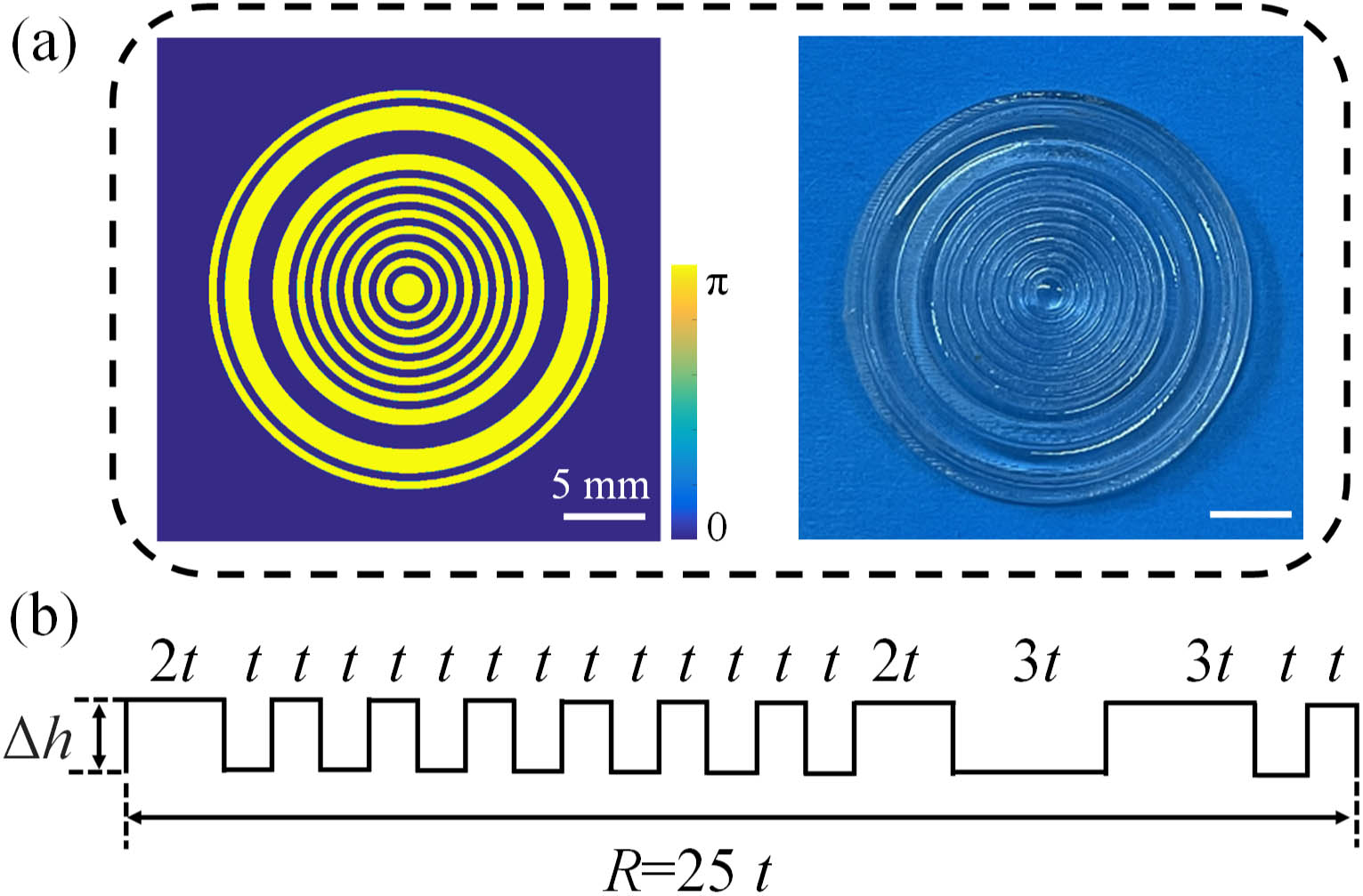
Photosensitive standard resin (PSR) is selected as the 3D printing material. Its transmittance and the refractive index are 82% and 1.66 at 278.6 GHz, respectively[31]. It is shown in Fig. 1(a) that the yellow concentric rings have a phase modulation of
This BDL is fabricated by layer superposition using selective curing printing technique (J850 Pro, Stratasys) with the average thickness of 14 µm of each layer. The liquid tank is filled with liquid PSR. At the beginning of the forming process, the lifting workbench is one layer below the liquid level. The PSR in the scanned area is rapidly cured to a thin sheet when irradiated by a converged laser beam. Once one layer is fabricated, the workbench drops a constant height and cures another layer. The minimum lateral printing size of this printer is 100 µm, which satisfies the accuracy requirements of the BDL working at 278.6 GHz.
The intensity distribution at the back focal plane is simulated by angular spectrum propagation[25] using MATLAB when the effective area of the BDL is irradiated normally by a 278.6 GHz parallel beam. The pixel pitch is identical with the detector, while the computation window is
![]()
Figure 2.Comparison between simulated and measured intensity distributions at the back focal plane of the THz BDL. (a) Simulated distribution when the irradiated diameter of the BDL is 25 mm; (b) vertical profile through the beam center in (a); (c) experimental distribution when the irradiated diameter is 20 mm; and (d) corresponding vertical profile; (e) simulated distribution when the irradiated diameter is 20 mm; and (f) corresponding vertical profile.
Figure 2(c) shows the intensity distribution recorded by a microbolometer (MICROXCAM-384i-THz, INO) at the back focal plane, with a pixel pitch of
The normalized axial intensity distributions of the beam emitted from the BDL are also plotted in Fig. 3. The propagation range is 10 mm to 50 mm, with an axial interval of 0.3 mm. Figure 3(a) shows the simulated distribution when the BDL is fully irradiated like Fig. 2(c). It is shown that the focal length and depth are
![]()
Figure 3.Comparison between simulated and measured intensity distributions at the x–z plane. (a) Simulated distribution when the diameter of incident beam is 25 mm; (b) measured and (c) simulated distributions when the irradiated diameter is 20 mm.
4. Imaging Results
The diagram of the experimental setup is illustrated in Fig. 4. To prevent overexposure of the detector, an attenuator with 3% transmittance is placed downstream the source. The divergent beam is collimated by a TCL to form a quasi-parallel beam with a diameter of
![]()
Figure 4.Schematic of THz BDL scanning imaging setup. APD, avalanche photodiode; TCL, transmissive convex lens; BDL, binary diffractive lens.
To quantify the resolution of the THz BDL scanning imaging setup, a 1D resolution test target is fabricated by punching vertical bars with different widths on a stainless-steel plate with a thickness of 2 mm. The scanning region is plotted using a yellow dashed line in Fig. 5(a), in which the smallest width and spacing of the bars are both 0.8 mm, and the largest width and spacing are 2.5 mm. Figure 5(b) illustrates the imaging result using BDL without extra image processing on purpose. The targets with the width of 1, 1.2, 1.5, 1.8, 2, and 2.5 mm can be recognized. Although the edge diffraction from the hollow bars has a negative effect on image quality, there is a clear trend that the signal-to-noise ratio (SNR) increases with width extension of the bars.
![]()
Figure 5.THz imaging results of the resolution test target. (a) Photo; (b) intensity image by BDL scanning; (c) intensity image by TCL scanning; (d) comparison of line scans.
For comparison, a TCL (TPX-D25, 1-F25,
Another sample is a baseplate embossed with the letter “H” with a height of 2 mm. More size parameters are denoted in Fig. 6(a). It is fabricated by 3D printing using visually opaque resin, the transmittance and the refractive index of which are 88% and 1.65 at 278.6 GHz, respectively[31]. The scanning area is
![]()
Figure 6.THz imaging results of a resin sample. (a) Photo of the sample with lid; intensity images of (b) uncovered and (c) covered sample by TCL scanning; intensity images of (d) uncovered and (e) covered sample by BDL scanning.
The imaging results of the sample without or with the lid scanned by the TCL and BDL are shown in Figs. 6(b)–6(e), respectively. In each figure, the blue curve in the subplot corresponds to the position plotted by the white dashed line, indicating the edge undulation. The comparison shows that the letter in Fig. 6(b) has a clearer silhouette than that in Fig. 6(c). In addition, the area of the letter in Fig. 6(b) is
5. Summary and Discussion
In this Letter, a binary diffractive lens achieving subwavelength focusing is proposed at 278.6 GHz. The diameter of the focal spot is modulated by sets of concentric rings with constant step height and optimized radii; thus, this component can be easily fabricated by 3D printing. The FWHM of the focal spot is 0.65 mm, which varies with the irradiated area of the BDL. A THz scanning imaging setup is constructed based on this low-cost lens, achieving 1 mm (
The diameter of this BDL is mainly determined by two factors. First, its efficient area depends on the diameter of the illumination THz beam. To expand a bigger beam, a larger lens upstream from the BDL is required with incremental absorption and transmission loss to the THz radiation. Meanwhile, a reasonable margin of the BDL, 20% in our case, is also very helpful for the alignment in this visually invisible illumination scenario. Second, the computing time based on simulated annealing algorithm would increase with the number of rings. It is feasible to fabricate a bigger BDL, which may further enhance the diffraction efficiency and converge a smaller spot. However, smaller FWHM refers to the main lobe with lower intensity; accompanying sidelobes with stronger intensity would degrade the imaging quality. It is noted that the TCL has higher THz transmission efficiency (
Further study will be conducted to enhance the performance of the BDL and the imaging setup. First, it is feasible to suppress sidelobes by optimizing the BDL structure using high efficiency design approaches, e.g., a deep-learning framework. Second, the nonuniform THz beam is also a main factor degrading the convergence ability of the BDL. It is necessary to develop THz spatial filters based on extraordinary optical transmission to polish the incident beam. Third, for raster scanning when using a cell detector, it is difficult to investigate dynamic phenomena beyond the potential mechanical translation error. A fast scanning system constituted by a 2D galvanometer and array detector is expected to match well with THz BDL scanning.
References
[1] D. A. Lima, J. Song, X. R. Li, A. Portieri, Y. C. Shen, J. A. Zeitler, H. Lin. Review of terahertz pulsed imaging for pharmaceutical film coating analysis. Sensors, 20, 1441(2020).
[2] M. Wan, J. J. Healy, J. T. Sheridan. Terahertz phase imaging and biomedical applications. Opt. Laser Technol., 122, 105859(2020).
[3] Q. Liang, G. Klatt, N. Kraub, O. Kukharenko, T. Dekorsy. Origin of potential errors in the quantitative determination of terahertz optical properties in time-domain terahertz spectroscopy. Chin. Opt. Lett., 13, 093001(2015).
[4] L. Rong, T. Latychevskaia, D. Wang, X. Zhou, Y. Wang. Terahertz in-line digital holography of dragonfly hindwing: amplitude and phase reconstruction at enhanced resolution by extrapolation. Opt. Express, 22, 17236(2014).
[5] H. Huang, L. Rong, D. Wang, W. Li, Q. Deng, B. Li, Y. Wang, Z. Zhan, X. Wang, W. Wu. Synthetic aperture in terahertz in-line digital holography for resolution enhancement. Appl. Opt., 55, A43(2016).
[6] L. Rong, F. Tan, D. Wang, Y. Zhang, K. Li, J. Zhao, Y. Wang. High-resolution terahertz ptychography using divergent illumination and extrapolation algorithm. Opt. Laser Technol., 147, 106729(2021).
[7] Z. Li, Q. Yan, Y. Qin, W. Kong, M. Zou, X. Zhou, Z. You, P. Cheng. Resolution enhancement in terahertz digital in-line holography by sparsity-based extrapolation. J. Infrared Millim. Terahertz Waves, 42, 479(2021).
[8] A. Bitman, S. Goldring, I. Moshe, Z. Zalevsky. Computed tomography using broadband Bessel THz beams and phase contrast. Opt. Lett., 39, 1925(2014).
[9] Y. L. Lim, K. Bertling, T. Taimre, T. Gillespie, C. Glenn, A. Robinson, D. Indjin, Y. Han, L. Li, E. H. Linfield, A. G. Davies, P. Dean, A. D. Raki. Coherent imaging using laser feedback interferometry with pulsed-mode terahertz quantum cascade lasers. Opt. Express, 27, 10221(2019).
[10] M. Wan, H. Yuan, J. J. Healy, J. T. Sheridan. Terahertz confocal imaging: polarization and sectioning characteristics. Opt. Lasers Eng., 134, 106182(2020).
[11] Y. Takida, K. Nawata, H. Minamide. Injection-seeded backward terahertz-wave parametric oscillator. APL Photonics, 5, 061301(2020).
[12] D. Wang, X. Jin, J. Zhao, Y. Wang, L. Rong, J. J. Healy. Continuous-wave terahertz diffraction tomography for measuring three-dimensional refractive index maps. Chin. Opt. Lett., 19, 123701(2021).
[13] B. Li, D. Wang, L. Rong, C. Zhai, Y. Wang, J. Zhao. Application of continuous-wave terahertz computed tomography for the analysis of chicken bone structure. Opt. Eng., 57, 023105(2018).
[14] L. Chen, Y. Wang, D. Xu, Y. Ren, Y. He, C. Li, C. Zhang, L. Tang, C. Yan, J. Yao. Terahertz computed tomography of high-refractive-index objects based on refractive index matching. IEEE Photon. J., 10, 5900813(2018).
[15] N. V. Chernomyrdin, A. O. Schadko, S. P. Lebedev, V. L. Tolstoguzov, V. N. Kurlov, I. V. Reshetov, I. E. Spektor, M. Skorobogatiy, S. O. Yurchenko, K. I. Zaytsev. Solid immersion terahertz imaging with sub-wavelength resolution. Appl. Phys. Lett., 110, 221109(2017).
[16] Z. Yin, Q. Zheng, K. Wang, G. Kai, S. Fei, H. Zhou, Y. Sun, Q. Zhou, J. Gao, L. Luo. Tunable dual-band terahertz metalens based on stacked graphene metasurfaces. Opt. Commun., 429, 41(2018).
[17] X. Wang, J. Zhao, M. Li, G. Jiang, X. Hu, N. Zhang, H. Zhai, W. Liu. Tight focus and field enhancement of terahertz waves using a probe based on spoof surface plasmons. Acta. Phys. Sin., 69, 054201(2020).
[18] L. Minkevičius, D. Jokubauskis, I. Kašalynas, S. Orlov, A. Urbas, G. Valušis. Bessel terahertz imaging with enhanced contrast realized by silicon multi-phase diffractive optics. Opt. Express, 27, 36358(2019).
[19] D. Ruan, Z. Li, L. Du, X. Zhou, L. Zhu, C. Lin, M. Yang, G. Chen, W. Yuan, G. Liang, Z. Wen. Realizing a terahertz far-field sub-diffraction optical needle with sub-wavelength concentric ring structure array. Appl. Opt., 57, 7905(2018).
[20] A. Iba, C. W. Domier, M. Ikeda, A. Mase, M. Nakajima, A. V. Pham, N. C. Luhmann. Subdiffraction focusing with a long focal length using a terahertz-wave super-oscillatory lens. Opt. Lett., 46, 4912(2021).
[21] Z. Zhang, X. Wei, C. Liu, K. Wang, J. Liu, Z. Yang. Rapid fabrication of terahertz lens via three-dimensional printing technology. Chin. Opt. Lett., 13, 022201(2015).
[22] J. Seifert, G. Hernadz, M. Koch. Terahertz beam steering using active diffraction grating fabricated by 3D printing. Opt. Express, 28, 21737(2020).
[23] D. Rohrbach, B. J. Kang, T. Feurer. 3D-printed THz wave- and phase-plates. Opt. Express, 29, 27160(2021).
[24] C. Liu, J. Liu, L. Niu, X. Wei, K. Wang, Z. Yang. Terahertz circular Airy vortex beams. Sci. Rep., 7, 3891(2017).
[25] W. Goodman. Introduction to Fourier Optics(2005).
[26] T. R. M. Sales, G. M. Morris. Diffractive superresolution elements. J. Opt. Soc. Am. A, 14, 1637(1997).
[27] S. Mukhopadhyay, L. Hazra. Pareto optimality between width of central lobe and peak sidelobe intensity in the far-field pattern of lossless phase-only filters for enhancement of transverse resolution. Appl. Opt., 54, 9205(2015).
[28] H. Fei, J. Yu, Y. Tan, C. Wei, K. Sugioka. Tailoring femtosecond 1.5-µm Bessel beams for manufacturing high-aspect-ratio through-silicon vias open. Sci. Rep., 7, 40785(2017).
[29] X. Wan, B. Shen, R. Menon. Diffractive lens design for optimized focusing. J. Opt. Soc. Am. A, 31, B27(2014).
[30] S. Kirkpatrick, C. D. Gelatt, M. P. Vecchi. Optimization by simulated annealing. Science, 220, 671(1983).
[31] S. F. Busch, M. Weidenbach, M. Fey, F. Schäfer, M. Koch, T. Probst. Optical properties of 3D printable plastics in the THz regime and their application for 3D printed THz optics. J. Infrared Millim. Terahertz Waves, 35, 993(2014).
[32] K. Huang, H. Ye, J. Teng, S. P. Yeo, B. L. Yanchuk, C. W. Qiu. Optimization-free super oscillatory lens using phase and amplitude masks. Laser Photon. Rev., 8, 152(2014).
[33] J. Lindberg. Mathematical concepts of optical superresolution. J. Opt., 14, 083001(2012).


Set citation alerts for the article
Please enter your email address

© Copyright 2018-2021 | Chinese Laser Press. All Rights Reserved 沪ICP备15018463号-20