
Chunlei Yu, Meng Wang, Suya Feng, Shikai Wang, Fan Wang, Fengguang Lou, Lei Zhang, Danping Chen, Lili Hu. Research Progress on Ytterbium-Doped Large Mode Area Photonic Crystal Fibers[J]. Laser & Optoelectronics Progress, 2019, 56(17): 170602
- Laser & Optoelectronics Progress
- Vol. 56, Issue 17, 170602 (2019)
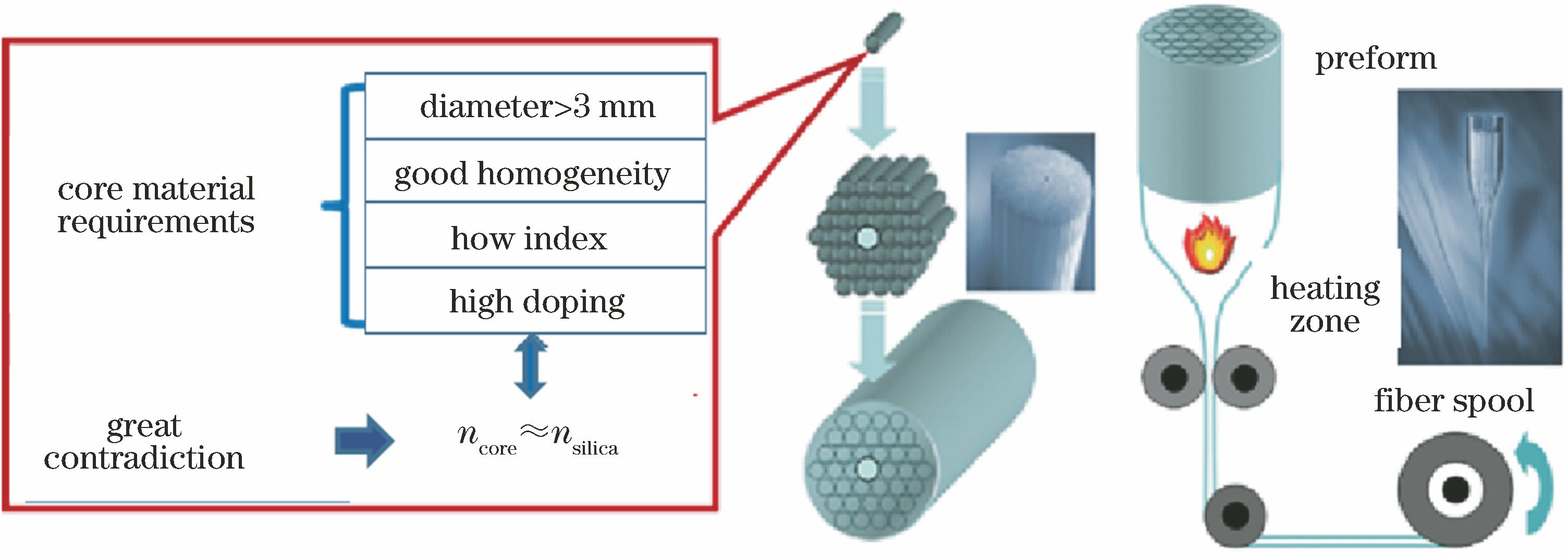
Fig. 1. Requirements for mandrels in high brightness Yb-doped LMA-PCF
![MCVD process flowchart[26]](/richHtml/lop/2019/56/17/170602/img_2.jpg)
Fig. 2. MCVD process flowchart[26]
Fig. 3. Preparation of preform by DND process[35]
Fig. 4. Powder sintering process[37]
Fig. 5. Process of phase separation to prepare porous[43]
Fig. 6. Fabrication of rare earth doped optical fibers by phase separation method[45]
Fig. 7. Fabrication of large mode ytterbium doped fiber process by sol-gel process
Fig. 8. (a) Glass forming region of Yb/Al/P doped silica glass; (b) magnified view of glass forming region in area with high content of SiO224
Fig. 9. Performances of Yb3+ in YAP series samples[29]. (a) Absorption spectrum; (b) emission spectrum
Fig. 10. Raman spectra of Yb3+/Al3+/P5+ doped silica glass[26]
Fig. 11. Structure of Yb3+/Al3+/P5+ co-doped quartz glass[26]
Fig. 12. Effects of Yb2O3, Al2O3, P/Al ratio, and AlPO4 on refractive index of silica glass[26,29,31]
Fig. 13. Photographs of Yb-doped quartz glass mandrels
Fig. 14. Photographs of photonic crystal fibers and composition distribution of fiber cores. (a) PCF cross-sectional photographs; (b) EPMA line scan maps of Yb, Al, P, and F elements in fiber core
Fig. 15. Laser amplification system and output laser characteristics. (a) Main oscillator power amplifier system; (b) average pulse amplification power versus pump power. Insets are beam qualities at 120 W and 272 W, respectively
Fig. 16. Photo of photonic crystal fiber end face and laser amplification performance. (a) SEM photograph of large mode area PCF with 75 μm core diameter; (b) average pulse amplification power versus pump power
Fig. 17. Development of LMA-PCF fabricated by sol-gel method
|
Table 1. Development of ytterbium doped silica fibers using sol-gel method
|
Table 2. Characteristics of Yb-doped silica glass rods with different compositions
|
Table 3. Performance comparison between Yb-doped quartz glass mandrel prepared by our research group and Heraeus products

Set citation alerts for the article
Please enter your email address
© Copyright 2018-2021 | Chinese Laser Press. All Rights Reserved 沪ICP备15018463号-20