[1] T. Tajima, J. M. Dawson. Phys. Rev. Lett., 43, 267(1979).
[2] E. Esarey, P. Sprangle, J. Krall, A. Ting. IEEE Trans. Plasma Sci., 24, 252(1996).
[3] E. Esarey, C. B. Schroeder, W. P. Leemans. Rev. Mod. Phys., 81, 1229(2009).
[4] S. M. Hooker. Nat. Photonics, 7, 775(2013).
[5] X. Wang, R. Zgadzaj, N. Fazel, Z. Li, S. A. Yi, X. Zhang, W. Henderson, Y.-Y. Chang, R. Korzekwa, H.-E. Tsai, C.-H. Pai, H. Quevedo, G. Dyer, E. Gaul, M. Martinez, A. C. Bernstein, T. Borger, M. Spinks, M. Donovan, V. Khudik, G. Shvets, T. Ditmire, M. C. Downer. Nat. Commun., 4(2013).
[6] W. P. Leemans, B. Nagler, A. J. Gonsalves, Cs. Tóth, K. Nakamura, C. G. R. Geddes, E. Esarey, C. B. Schroeder, S. M. Hooker. Nat. Phys., 2, 696(2006).
[7] W. P. Leemans, A. J. Gonsalves, H.-S. Mao, K. Nakamura, C. Benedetti, C. B. Schroeder, Cs. Tóth, J. Daniels, D. E. Mittelberger, S. S. Bulanov, J.-L. Vay, C. G. R. Geddes, E. Esarey. Phys. Rev. Lett., 113, 245002(2014).
[8] A. J. Gonsalves, K. Nakamura, J. Daniels, C. Benedetti, C. Pieronek, T. C. H. de Raadt, S. Steinke, J. H. Bin, S. S. Bulanov, J. van Tilborg, C. G. R. Geddes, C. B. Schroeder, Cs. Tóth, E. Esarey, K. Swanson, L. Fan-Chiang, G. Bagdasarov, N. Bobrova, V. Gasilov, G. Korn, P. Sasorov, W. P. Leemans. Phys. Rev. Lett., 122, 084801(2019).
[9] R. Weingartner, S. Raith, A. Popp, S. Chou, J. Wenz, K. Khrennikov, M. Heigoldt, A. R. Maier, N. Kajumba, M. Fuchs, B. Zeitler, F. Krausz, S. Karsch, F. Grüner. Phys. Rev. Spec. Top. Accel. Beams, 15, 111302(2012).
[10] G. R. Plateau, C. G. R. Geddes, D. B. Thorn, M. Chen, C. Benedetti, E. Esarey, A. J. Gonsalves, N. H. Matlis, K. Nakamura, C. B. Schroeder, S. Shiraishi, T. Sokollik, J. van Tilborg, Cs. Toth, S. Trotsenko, T. S. Kim, M. Battaglia, Th. Stöhlker, W. P. Leemans. Phys. Rev. Lett., 109, 064802(2012).
[11] O. Lundh, J. Lim, C. Rechatin, L. Ammoura, A. Ben-Ismaïl, X. Davoine, G. Gallot, J.-P. Goddet, E. Lefebvre, V. Malka, J. Faure. Nat. Phys., 7, 219(2011).
[12] A. Buck, M. Nicolai, K. Schmid, C. M. S. Sears, A. Sävert, J. M. Mikhailova, F. Krausz, M. C. Kaluza, L. Veisz. Nat. Phys., 7, 543(2011).
[13] J. P. Couperus, R. Pausch, A. Köhler, O. Zarini, J. M. Krämer, M. Garten, A. Huebl, R. Gebhardt, U. Helbig, S. Bock, K. Zeil, A. Debus, M. Bussmann, U. Schramm, A. Irman. Nat. Commun., 8, 487(2017).
[14] C. G. R. Geddes, Cs. Toth, J. van Tilborg, E. Esarey, C. B. Schroeder, D. Bruhwiler, C. Nieter, J. Cary, W. P. Leemans. Nature, 431, 538(2004).
[15] J. Faure, Y. Glinec, A. Pukhov, S. Kiselev, S. Gordienko, E. Lefebvre, J.-P. Rousseau, F. Burgy, V. Malka. Nature, 431, 541(2004).
[16] S. P. D. Mangles, C. D. Murphy, Z. Najmudin, A. G. R. Thomas, J. L. Collier, A. E. Dangor, E. J. Divall, P. S. Foster, J. G. Gallacher, C. J. Hooker, D. A. Jaroszynski, A. J. Langley, W. B. Mori, P. A. Norreys, F. S. Tsung, R. Viskup, B. R. Walton, K. Krushelnick. Nature, 431, 535(2004).
[17] A. Zigler, Y. Ehrlich, C. Cohen, J. Krall, P. Sprangle. J. Opt. Soc. Am. B, 13, 68(1996).
[18] Y. Ehrlich, C. Cohen, A. Zigler, J. Krall, P. Sprangle, E. Esarey. Phys. Rev. Lett., 77, 4186(1996).
[19] Y. Ehrlich, C. Cohen, D. Kaganovich, A. Zigler, R. F. Hubbard, P. Sprangle, E. Esarey. J. Opt. Soc. Am. B, 15, 2416(1998).
[20] D. Kaganovich, P. V. Sasorov, Y. Ehrlich, C. Cohen, A. Zigler. Appl. Phys. Lett., 71, 2925(1997).
[21] D. Kaganovich, A. Ting, C. I. Moore, A. Zigler, H. R. Burris, Y. Ehrlich, R. Hubbard, P. Sprangle. Phys. Rev. E, 59, R4769(1999).
[22] R. F. Hubbard, Y. Ehrlich, D. Kaganovich, C. Cohen, C. I. Moore, P. Sprangle, A. Ting, A. Zigler. AIP Conf. Proc., 472, 394(1999).
[23] D. Kaganovich, P. Sasorov, C. Cohen, A. Zigler. Appl. Phys. Lett., 75, 772(1999).
[24] T. Hosokai, M. Kando, H. Dewa, H. Kotaki, S. Kondo, N. Hasegawa, K. Nakajima, K. Horioka. Opt. Lett., 25, 10(2000).
[25] E. Esarey, J. Krall, P. Sprangle. Phys. Rev. Lett., 72, 2887(1994).
[26] E. Esarey, P. Sprangle, J. Krall, A. Ting. IEEE J. Quantum Electron., 33, 1879(1997).
[27] A. J. Gonsalves, K. Nakamura, C. Lin, D. Panasenko, S. Shiraishi, T. Sokollik, C. Benedetti, C. B. Schroeder, C. G. R. Geddes, J. van Tilborg, J. Osterhoff, E. Esarey, C. Toth, W. P. Leemans. Nat. Phys., 7, 862(2011).
[28] M. Kirchen, S. Jalas, P. Messner, P. Winkler, T. Eichner, L. Hübner, T. Hülsenbusch, L. Jeppe, T. Parikh, M. Schnepp, A. R. Maier. Phys. Rev. Lett., 126, 174801(2021).
[29] N. H. Matlis, A. J. Gonsalves, S. Steinke, J. van Tilborg, B. Shaw, D. E. Mittelberger, C. G. R. Geddes, W. P. Leemans. J. Appl. Phys., 119, 074501(2016).
[30] L. Schaper, L. Goldberg, T. Kleinwächter, J.-P. Schwinkendorf, J. Osterhoff. Nucl. Instrum. Methods Phys. Res. Sect. A, 740, 208(2014).
[31] N. H. Matlis, A. J. Gonsalves, S. Steinke, J. van Tilborg, E. H. Matlis, B. Shaw, D. E. Mittelberger, C. G. R. Geddes, W. P. Leemans. J. Appl. Phys., 118, 204506(2015).
[32] M. Fuchs, R. Weingartner, A. Popp, Z. Major, S. Becker, J. Osterhoff, I. Cortrie, B. Zeitler, R. Hörlein, G. D. Tsakiris, U. Schramm, T. P. Rowlands-Rees, S. M. Hooker, D. Habs, F. Krausz, S. Karsch, F. Grüner. Nat. Phys., 5, 826(2009).
[33] A. Butler, A. J. Gonsalves, C. M. McKenna, D. J. Spence, S. M. Hooker, S. Sebban, T. Mocek, I. Bettaibi, B. Cros. Phys. Rev. Lett., 91, 205001(2003).
[34] M. Chen, J. Luo, F.-Y. Li, F. Liu, Z.-M. Sheng, J. Zhang. Light Sci. Appl., 5, e16015(2016).
[35] E. A. Gibson, X. Zhang, T. Popmintchev, A. Paul, N. Wagner, A. Lytle, I. P. Christov, M. M. Murnane, H. C. Kapteyn. IEEE J. Select. Top. Quantum Electron., 10, 1339(2004).
[36] J. Luo, M. Chen, W. Y. Wu, S. M. Weng, Z. M. Sheng, C. B. Schroeder, D. A. Jaroszynski, E. Esarey, W. P. Leemans, W. B. Mori, J. Zhang. Phys. Rev. Lett., 120, 154801(2018).
[37] K. Nakajima. Light Sci. Appl., 7, 21(2018).
[38] A. Zigler, M. Botton, Y. Ferber, G. Johansson, O. Pollak, E. Dekel, F. Filippi, M. P. Anania, F. Bisesto, R. Pompili, M. Ferrario. Appl. Phys. Lett., 113, 183505(2018).
[39] V. Shpakov, M. P. Anania, M. Bellaveglia, A. Biagioni, F. Bisesto, F. Cardelli, M. Cesarini, E. Chiadroni, A. Cianchi, G. Costa, M. Croia, A. Del Dotto, D. Di Giovenale, M. Diomede, M. Ferrario, F. Filippi, A. Giribono, V. Lollo, M. Marongiu, V. Martinelli, A. Mostacci, L. Piersanti, G. Di Pirro, R. Pompili, S. Romeo, J. Scifo, C. Vaccarezza, F. Villa, A. Zigler. Phys. Rev. Lett., 122, 114801(2019).
[40] R. D'Arcy, S. Wesch, A. Aschikhin, S. Bohlen, C. Behrens, M. J. Garland, L. Goldberg, P. Gonzalez, A. Knetsch, V. Libov, A. Martinez de la Ossa, M. Meisel, T. J. Mehrling, P. Niknejadi, K. Poder, J.-H. Röckemann, L. Schaper, B. Schmidt, S. Schröder, C. Palmer, J.-P. Schwinkendorf, B. Sheeran, M. J. V. Streeter, G. Tauscher, V. Wacker, J. Osterhoff. Phys. Rev. Lett., 122, 034801(2019).
[41] R. Pompili, D. Alesini, M. P. Anania, M. Behtouei, M. Bellaveglia, A. Biagioni, F. G. Bisesto, M. Cesarini, E. Chiadroni, A. Cianchi, G. Costa, M. Croia, A. Del Dotto, D. Di Giovenale, M. Diomede, F. Dipace, M. Ferrario, A. Giribono, V. Lollo, L. Magnisi, M. Marongiu, A. Mostacci, L. Piersanti, G. Di Pirro, S. Romeo, A. R. Rossi, J. Scifo, V. Shpakov, C. Vaccarezza, F. Villa, A. Zigler. Nat. Phys., 17, 499(2021).
[42] J. van Tilborg, S. Steinke, C. G. R. Geddes, N. H. Matlis, B. H. Shaw, A. J. Gonsalves, J. V. Huijts, K. Nakamura, J. Daniels, C. B. Schroeder, C. Benedetti, E. Esarey, S. S. Bulanov, N. A. Bobrova, P. V. Sasorov, W. P. Leemans. Phys. Rev. Lett., 115, 184802(2015).
[43] R. Pompili, M. P. Anania, M. Bellaveglia, A. Biagioni, S. Bini, F. Bisesto, E. Brentegani, G. Castorina, E. Chiadroni, A. Cianchi, M. Croia, D. Di Giovenale, M. Ferrario, F. Filippi, A. Giribono, V. Lollo, A. Marocchino, M. Marongiu, A. Mostacci, G. Di Pirro, S. Romeo, A. R. Rossi, J. Scifo, V. Shpakov, C. Vaccarezza, F. Villa, A. Zigler. Appl. Phys. Lett., 110, 104101(2017).
[44] J. van Tilborg, S. K. Barber, C. Benedetti, C. B. Schroeder, F. Isono, H.-E. Tsai, C. G. R. Geddes, W. P. Leemans. Phys. Plasmas, 25, 056702(2018).
[45] C. A. Lindstrøm, E. Adli, G. Boyle, R. Corsini, A. E. Dyson, W. Farabolini, S. M. Hooker, M. Meisel, J. Osterhoff, J.-H. Röckemann, L. Schaper, K. N. Sjobak. Phys. Rev. Lett., 121, 194801(2018).
[46] R. Pompili, M. Anania, M. Bellaveglia, A. Biagioni, S. Bini, F. Bisesto, E. Brentegani, F. Cardelli, G. Castorina, E. Chiadroni, A. Cianchi, O. Coiro, G. Costa, M. Croia, D. Di Giovenale, M. Ferrario, F. Filippi, A. Giribono, V. Lollo, A. Marocchino, M. Marongiu, V. Martinelli, A. Mostacci, D. Pellegrini, L. Piersanti, G. Di Pirro, S. Romeo, A. Rossi, J. Scifo, V. Shpakov, A. Stella, C. Vaccarezza, F. Villa, A. Zigler. Phys. Rev. Lett., 121, 174801(2018).
[47] R. Pompili, G. Castorina, M. Ferrario, A. Marocchino, A. Zigler. AIP Adv., 8, 015326(2018).
[48] A. F. Pousa, A. Martinez de la Ossa, R. Brinkmann, R. W. Assmann. Phys. Rev. Lett., 123, 054801(2019).
[49] R. Pompili, E. Chiadroni, A. Cianchi, A. Del Dotto, L. Faillace, M. Ferrario, P. Iovine, M. R. Masullo. Phys. Rev. Accel. Beams, 22, 121302(2019).
[50] S. K. Barber, J. H. Bin, A. J. Gonsalves, F. Isono, J. van Tilborg, S. Steinke, K. Nakamura, A. Zingale, N. A. Czapla, D. Schumacher, C. B. Schroeder, C. G. R. Geddes, W. P. Leemans, E. Esarey. Appl. Phys. Lett., 116, 234108(2020).
[51] T. Yang, H. Cheng, Y. Yan, M. Wu, D. Li, Y. Li, Y. Xia, C. Lin, X. Yan. Phys. Rev. Accel. Beams, 24, 031301(2021).
[52] J. Bin, L. Obst-Huebl, J.-H. Mao, K. Nakamura, L. D. Geulig, H. Chang, Q. Ji, L. He, J. De Chant, Z. Kober, A. J. Gonsalves, S. Bulanov, S. E. Celniker, C. B. Schroeder, C. G. R. Geddes, E. Esarey, B. A. Simmons, T. Schenkel, E. A. Blakely, S. Steinke, A. M. Snijders. Sci. Rep., 12, 1484(2022).
[53] P. Sprangle, E. Esarey. Phys. Fluids B, 4, 2241(1992).
[54] P. Sprangle, E. Esarey, J. Krall, G. Joyce. Phys. Rev. Lett., 69, 2200(1992).
[55] P. Sprangle, B. Hafizi, J. R. Peñano. Phys. Rev. E, 61, 4381(2000).
[56] P. Jha, N. Wadhwani, A. K. Upadhyaya, G. Raj. Phys. Plasmas, 11, 3259(2004).
[57] E. Esarey, C. B. Schroeder, B. A. Shadwick, J. S. Wurtele, W. P. Leemans. Phys. Rev. Lett., 84, 3081(2000).
[58] C. Ren, B. J. Duda, R. G. Hemker, W. B. Mori, T. Katsouleas, T. M. Antonsen, P. Mora. Phys. Rev. E, 63, 026411(2001).
[59] P. Sprangle, J. R. Peñano, B. Hafizi. Phys. Rev. E, 66, 046418(2002).
[60] A. K. Upadhyay, G. Raj, R. K. Mishra, A. Malviya, P. Jha. Phys. Plasmas, 14, 093107(2007).
[61] A. K. Upadhyay, G. Raj, R. K. Mishra, P. Jha. Phys. Plasmas, 14, 113105(2007).
[62] P. Sprangle, A. Ting, C. M. Tang. Phys. Rev. Lett., 59, 202(1987).
[63] P. Sprangle, A. Ting, C. M. Tang. Phys. Rev. A, 36, 2773(1987).
[64] C. Benedetti, C. B. Schroeder, E. Esarey, W. P. Leemans. Phys. Plasmas, 19, 053101(2012).
[65] E. Esarey, W. P. Leemans. Phys. Rev. E, 59, 1082(1999).
[66] L. Yu, H. M. Zhao, Q. Cao, X. Z. Zhu, J. L. Li, B. Y. Li, F. Liu, M. Chen, Z. M. Sheng. Plasma Phys. Control. Fusion, 64, 075009(2022).
[67] N. A. Bobrova, A. A. Esaulov, J.-I. Sakai, P. V. Sasorov, D. J. Spence, A. Butler, S. M. Hooker, S. V. Bulanov. Phys. Rev. E, 65, 016407(2001).
[68] B. H. P. Broks, K. Garloff, J. J. A. M. van der Mullen. Phys. Rev. E, 71, 016401(2005).
[69] D. J. Spence, S. M. Hooker. Phys. Rev. E, 63, 015401(2000).
[70] D. M. Gaudiosi, B. Reagan, T. Popmintchev, M. Grisham, M. Berrill, O. Cohen, B. C. Walker, M. M. Murnane, H. C. Kapteyn, J. J. Rocca. Phys. Rev. Lett., 96, 203001(2006).
[71] D. J. Spence, P. D. S. Burnett, S. M. Hooker. Opt. Lett., 24, 993(1999).
[72] F. Brandi, L. A. Gizzi. High Power Laser Sci. Eng., 7, e26(2019).
[73] A. J. Gonsalves, T. P. Rowlands-Rees, B. H. P. Broks, J. J. A. M. van der Mullen, S. M. Hooker. Phys. Rev. Lett., 98, 025002(2007).
[74] T. G. Jones, A. Ting, D. Kaganovich, C. I. Moore, P. Sprangle. Phys. Plasmas, 10, 4504(2003).
[75] J. Kim, V. L. J. Phung, K. Roh, M. Kim, K. Kang, H. Suk. Rev. Sci. Instrum., 92, 023511(2021).
[76] Y. Ping, I. Geltner, A. Morozov, S. Suckewer. Phys. Plasmas, 9, 4756(2002).
[77] H. S. Uhm, D. G. Jang, M. S. Kim, H. Suk. Phys. Plasmas, 19, 024501(2012).
[78] G. Bagdasarov, P. Sasorov, A. Boldarev, O. Olkhovskaya, V. Gasilov, A. J. Gonsalves, S. Barber, S. S. Bulanov, C. B. Schroeder, J. van Tilborg, E. Esarey, W. P. Leemans, T. Levato, D. Margarone, G. Korn, S. V. Bulanov. Phys. Plasmas, 24, 053111(2017).
[79] J. M. Garland, G. Tauscher, S. Bohlen, G. J. Boyle, R. D’Arcy, L. Goldberg, K. Põder, L. Schaper, B. Schmidt, J. Osterhoff. Rev. Sci. Instrum., 92, 013505(2021).
[80] A. Curcio, F. Bisesto, G. Costa, A. Biagioni, M. P. Anania, R. Pompili, M. Ferrario, M. Petrarca. Phys. Rev. E, 100, 053202(2019).
[81] X.-Z. Zhu, B.-Y. Li, F. Liu, J.-L. Li, Z.-W. Bi, L. Lu, X.-H. Yuan, W.-C. Yan, M. Chen, L.-M. Chen, Z.-M. Sheng, J. Zhang. Acta Phys. Sin., 71, 095202(2022).
[82] A. Biagioni, M.P. Anania, M. Bellaveglia, E. Chiadroni, A. Cianchi, D. Di Giovenale, G. Di Pirro, M. Ferrario, F. Filippi, A. Mostacci, R. Pompili, V. Shpakov, C. Vaccarezza, F. Villa, A. Zigler. J. Instrum., 11, C08003(2016).
[83] P. S. Antsiferov, M. R. Akdim, H. T. van Dam. Rev. Sci. Instrum., 78, 123107(2007).
[84] J. Liu, W. Li, J. Liu, Z. Qin, W. Wang, R. Qi, Z. Zhang, C. Yu, M. Fang, K. Feng, Y. Wu, C. Wang, R. Li. AIP Adv., 8, 105204(2018).
[85] T. P. Rowlands-Rees, C. Kamperidis, S. Kneip, A. J. Gonsalves, S. P. D. Mangles, J. G. Gallacher, E. Brunetti, T. Ibbotson, C. D. Murphy, P. S. Foster, M. J. V. Streeter, F. Budde, P. A. Norreys, D. A. Jaroszynski, K. Krushelnick, Z. Najmudin, S. M. Hooker. Phys. Rev. Lett., 100, 105005(2008).
[86] T. G. Jones, K. Krushelnick, A. Ting, D. Kaganovich, C. I. Moore, A. Morozov. Rev. Sci. Instrum., 73, 2259-2265(2002).
[87] J. Daniels, J. van Tilborg, A. J. Gonsalves, C. B. Schroeder, C. Benedetti, E. Esarey, W. P. Leemans. Phys. Plasmas, 22, 073112(2015).
[88] J. van Tilborg, A. J. Gonsalves, E. H. Esarey, C. B. Schroeder, W. P. Leemans. Opt. Lett., 43, 2776(2018).
[89] J. van Tilborg, A. J. Gonsalves, E. Esarey, C. B. Schroeder, W. P. Leemans. Phys. Plasmas, 26, 023106(2019).
[90] A. J. Gonsalves, K. Nakamura, C. Lin, J. Osterhoff, S. Shiraishi, C. B. Schroeder, C. G. R. Geddes, E. Esarey Cs. Tóth, W. P. Leemans. Phys. Plasmas, 17(2010).
[91] M. Turner, A. J. Gonsalves, S. S. Bulanov, C. Benedetti, N. A. Bobrova, V. A. Gasilov, P. V. Sasorov, G. Korn, K. Nakamura, J. van Tilborg, C. G. Geddes, C. B. Schroeder, E. Esarey. High Power Laser Sci. Eng., 9, e17(2021).
[92] B. Broks, J. van Dijk, H. Bastiaens, K. Boller, J. van der Mullen. J. Phys. D, 39, 2384(2006).
[93] V. V. Kotlyar, A. A. Kovalev. J. Opt. Soc. Am. A, 27, 372(2010).
[94] A. E. Siegman. Lasers(1986).
[95] A. D. Buckingham, C. Graham. Proc. R. Soc. Lond. Ser. A, 337, 275(1974).
[96] J. G. Zhu, M. J. Wu, Q. Liao, Y. X. Geng, K. Zhu, C. C. Li, X. H. Xu, D. Y. Li, Y. R. Shou, T. Yang, P. J. Wang, D. H. Wang, J. J. Wang, C. E. Chen, X. T. He, Y. Y. Zhao, W. J. Ma, H. Y. Lu, T. Tajima, C. Lin, X. Q. Yan. Phys. Rev. Accel. Beams, 22, 061302(2019).
[97] R. Fletcher. Practical Methods of Optimization: Unconstrained Optimization(1980).
[98] X. Yuan, Y. Xu, R. Zhao, X. Hong, R. Lu, X. Feng, Y. Chen, J. Zou, C. Zhang, Y. Qin, Y. Zhu. Optics, 2, 87(2021).
[99] M. J. Druyvesteyn, F. M. Penning. Rev. Mod. Phys., 12, 87(1940).
[100] B. Mancinelli, L. Prevosto, J. C. Chamorro, F. O. Minotti, H. Kelly. Plasma Chem. Plasma Process., 38, 147(2018).
[101] T. D. Arber, K. Bennett, C. S. Brady, A. Lawrence-Douglas, M. G. Ramsay, N. J. Sircombe, P. Gillies, R. G. Evans, H. Schmitz, A. R. Bell, C. P. Ridgers. Plasma Phys. Controll. Fusion, 57, 113001(2015).
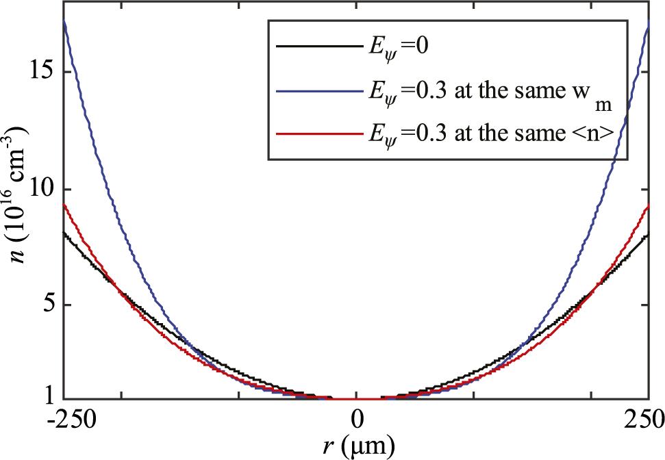
 as a function of radial position
  with axis density
  and matched spot size
  for a parabolic channel (black line) compared with a channel with an
  component with
  at the same
  (blue line) and a channel at the same
  (red line), respectively.
 with wavelength
  diffraction propagation by an ideal scattering boundary in a
  domain, where the data on the negative side of the radial axis are obtained by mirroring. (b) The normalized transverse
  profile at
  from calculation data (black line) and fitting the profile with the theoretical function
  (blue line) and the approximate Gaussian function (red line) for the channel-guided laser requirement.
 propagating in plasma with ideal matched spot size
  and
and  , where the data on the negative side of the radial axis are obtained by mirroring. The simulation domain corresponds to plasma channel radius
  and length
  cm. (b) The coupling parameter
  varying along the
  position in the solid blue line and the calculation values of
  (the upper subfigure) and
  (the lower one). (c) Discharge phenomenon of a gas-filled capillary viewed from the side.
 from experimental data shown with blue triangle marks and an exponential decline tendency of
  evolution shown with a dotted blue line. Both of the red curves above have the
  -axis on the right in red. Both of the blue curves have the
  -axis on the left in blue. Subfigure groups made up of a lower one, a measured profile and an upper one, a reconstructed profile via fitting results, in the same column from left to right, correspond to a laser pulse propagating through plasma channels at 245, 343, 458, 537 and 644 ns, respectively. All subfigures are under the unified ruler and color bar placed in the upper right corner inside.
 ,
,  and
and  respectively in the No. 9, No. 10 and No. 1 experiments correspondingly. (b) Reconstructed evolutions of density profile coefficient
  shown with triangle marks and exponential decline tendencies shown with broken lines with various styles of waveforms in No. 9 (red), No. 10 (blue) and No. 1 (black) experiments.
 shown with triangle marks and exponential decline tendencies shown with broken lines (a) with various high voltages
  , 20, 25 and 28 kV for He plasma in the No. 1 (red), No. 2 (blue), No. 3 (black) and No. 4 (green) experiments, (b) with various high voltages
  , 20, 25 and 28 kV for Ar plasma in the No. 5 (red), No. 6 (blue), No. 7 (black) and No. 8 (green) experiments. (c) Scaling of the exponential decline rate
  with high voltages for He plasma shown with the light-blue line and Ar plasma shown with the light-red line. The circle marks are in colors corresponding to those in (a) and (b).
 shown with triangle marks and exponential decline tendencies shown with broken lines (a) with various capillary diameters
  ,
,  and
and  in the No. 11 (red), No. 9 (blue) and No. 12 (black) experiments, and (b) with various pressures
  , 90 and 100 Torr in the No. 13 (red), No. 14 (blue) and No. 9 (black) experiments. (c) Scaling of the exponential decline rate
  with diameters. The circle marks are in colors corresponding to those in (a). (d) Scaling of the exponential decline rate
  with pressures. The circle marks are in colors corresponding to those in (b).
 nm of the front (red) end and
  nm of a


