• Photonics Research
  • Vol. 8, Issue 3, 311 (2020)
Zhenzhong Hao1, Li Zhang1, Wenbo Mao1, Ang Gao1, Xiaomei Gao1, Feng Gao1、2, Fang Bo1、2、*, Guoquan Zhang1、2、3, and Jingjun Xu1、2、4
Author Affiliations
  • 1MOE Key Laboratory of Weak-Light Nonlinear Photonics, TEDA Institute of Applied Physics and School of Physics, Nankai University, Tianjin 300457, China
  • 2Collaborative Innovation Center of Extreme Optics, Shanxi University, Taiyuan 030006, China
  • 3e-mail: zhanggq@nankai.edu.cn
  • 4e-mail: jjxu@nankai.edu.cn
  • show less
    DOI: 10.1364/PRJ.382535 Cite this Article Set citation alerts
    Zhenzhong Hao, Li Zhang, Wenbo Mao, Ang Gao, Xiaomei Gao, Feng Gao, Fang Bo, Guoquan Zhang, Jingjun Xu. Second-harmonic generation using d33 in periodically poled lithium niobate microdisk resonators[J]. Photonics Research, 2020, 8(3): 311 Copy Citation Text show less
    Flow diagram depicting the fabrication process of the PPLN microdisk resonators.
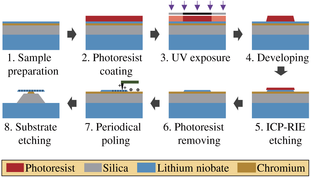
    Fig. 1. Flow diagram depicting the fabrication process of the PPLN microdisk resonators.
    Characteristics of a series of PPLN microdevices. (a) PFM image of the logo of Nankai University. (b) PPLN strips with 100 nm width and 100 nm distance. (c) PFM image of a PPLN microdisk without HF etching. (d) The measured Q factor of the PPLN microdisk. The inset represents the optical microscope image of a typical PPLN microdisk resonator. (e) Transmission spectrum of the resonator from 1540 to 1550 nm, showing the FSR of the pump mode.
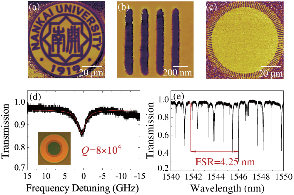
    Fig. 2. Characteristics of a series of PPLN microdevices. (a) PFM image of the logo of Nankai University. (b) PPLN strips with 100 nm width and 100 nm distance. (c) PFM image of a PPLN microdisk without HF etching. (d) The measured Q factor of the PPLN microdisk. The inset represents the optical microscope image of a typical PPLN microdisk resonator. (e) Transmission spectrum of the resonator from 1540 to 1550 nm, showing the FSR of the pump mode.
    Experimental setup for nonlinear optical experiments in PPLN microdisk resonators. PM, power meter; FPC, fiber polarization controller; AFG, arbitrary function generator; PD, photodetector.
    Fig. 3. Experimental setup for nonlinear optical experiments in PPLN microdisk resonators. PM, power meter; FPC, fiber polarization controller; AFG, arbitrary function generator; PD, photodetector.
    Characteristics of the WGMs involved in the SHG process. (a) Spectra of the pump (blue) and the generated nonlinear signal (red); the insets represent the simulated optical modes of the pump and the signal. (b) Relationship between the wavelength and the azimuthal quantum number of the pump and the signal modes.
    Fig. 4. Characteristics of the WGMs involved in the SHG process. (a) Spectra of the pump (blue) and the generated nonlinear signal (red); the insets represent the simulated optical modes of the pump and the signal. (b) Relationship between the wavelength and the azimuthal quantum number of the pump and the signal modes.
    Transmission (black) and scattering spectra polarized horizontally (blue) and vertically (red) for the (a) pump and (b) signal.
    Fig. 5. Transmission (black) and scattering spectra polarized horizontally (blue) and vertically (red) for the (a) pump and (b) signal.
    Conversion efficiency of the SHG signal in experiment and theory. (a) The conversion efficiency at low pump power detected in the experiment (black empty squares) and fitted in theory (red line). (b) Theoretical conversion efficiency showing the saturation under strong pump.
    Fig. 6. Conversion efficiency of the SHG signal in experiment and theory. (a) The conversion efficiency at low pump power detected in the experiment (black empty squares) and fitted in theory (red line). (b) Theoretical conversion efficiency showing the saturation under strong pump.
    (a) Schematic draft of an eccentric poling structure, where p represents the offset of the poling pattern with respect to the center of the resonator. (b) The effective nonlinear coefficient versus the period number with a chirp in the domain period, caused by a shift of the poling pattern with a 0.3 μm offset.
    Fig. 7. (a) Schematic draft of an eccentric poling structure, where p represents the offset of the poling pattern with respect to the center of the resonator. (b) The effective nonlinear coefficient versus the period number with a chirp in the domain period, caused by a shift of the poling pattern with a 0.3 μm offset.
    Transmission spectra of the PPLN microdisk coupled with a tapered fiber and their Lorentz fits for the (a) pump and (b) signal.
    Fig. 8. Transmission spectra of the PPLN microdisk coupled with a tapered fiber and their Lorentz fits for the (a) pump and (b) signal.
    Transmission spectra of the used PPLN microdisk and the attributed quantum numbers for each mode in the (a) 1550 nm band and (b) 780 nm band.
    Fig. 9. Transmission spectra of the used PPLN microdisk and the attributed quantum numbers for each mode in the (a) 1550 nm band and (b) 780 nm band.
    Zhenzhong Hao, Li Zhang, Wenbo Mao, Ang Gao, Xiaomei Gao, Feng Gao, Fang Bo, Guoquan Zhang, Jingjun Xu. Second-harmonic generation using d33 in periodically poled lithium niobate microdisk resonators[J]. Photonics Research, 2020, 8(3): 311
    Download Citation