1MOE Key Laboratory of Weak-Light Nonlinear Photonics, TEDA Institute of Applied Physics and School of Physics, Nankai University, Tianjin 300457, China
2Collaborative Innovation Center of Extreme Optics, Shanxi University, Taiyuan 030006, China
A fabrication process allowing for the production of periodically poled lithium niobate (PPLN) photonic devices with any domain pattern and unit size down to 200 nm is developed by combining semiconductor fabrication techniques and piezo-force-microscopy tips polarization. Based on this fabrication process, PPLN microdisk resonators with quality factors of were fabricated from a Z-cut lithium niobate film. Second-harmonic generation (SHG) utilizing in the whole cavity was demonstrated in a PPLN microdisk with a 2 μm-spatial-period radial domain pattern. The SHG conversion efficiency was measured to be . This work paves the way to fabricate complex PPLN photonic devices and to obtain efficient nonlinear optical effects that have wide applications in both classical and quantum optics.
1. INTRODUCTION
Lithium niobate (LN) microcavities with high quality factors show great potential in nonlinear optics due to the large nonlinear coefficients of LN crystal ( [1]) and strong light confinement. Such a light confinement can be realized both in time and in space (mode volume, ) by whispering gallery modes (WGMs) or microring cavities in the whole material transparent window (0.4–0.5 μm [1]). Until now, a series of research works on electro-optic modulators [2,3], wavelength convertors through second- and high-order harmonic generations [4–8], sum-frequency generation [9], four-wave mixing [10,11], optical parametric downconversion [12,13], and the Raman effect [14] were reported in LN WGM microcavities.
It is well known that momentum conservation (also referred to as phase matching, PM) is one of the most crucial conditions that needs to be satisfied to obtain efficient second-order nonlinear optical effects, besides energy conservation, multiple resonances, and spatial modes overlaps. PM can be fulfilled by using the birefringent effect of the material. One can realize PM by accurately controlling the shape of the microcavity [15], including its thickness, radius, and angle of wedge, and thereby the geometrical dispersion. Quasi-phase matching (QPM) [16] is an alternative to meet the phase-matching condition in ferroelectric materials. In the QPM regime, a spatial wave vector, introduced by periodically flipping the direction of the optical axis of the crystal, can be utilized to compensate for the original mismatch between the wave vectors of the pump and the generated light waves. QPM is very popular in LN photonic devices because of the utilization of [17,18], that is, the largest nonlinear coefficient of LN crystal.
Actually, the first LN microdisk resonator was fabricated from a periodically poled lithium niobate (PPLN) wafer with strip-shaped domain, where second-harmonic generation (SHG) was demonstrated [19]. Thereafter, Beckmann et al. reported a PPLN microdisk with off-centered radial domain pattern supporting optical parametric oscillation with broadband wavelength tuning performance [20]. However, the aforementioned PPLN disk resonators are of millimeter size, which prevents them from integration. Very recently, our group and Wolf et al. demonstrated the fabrication and SHG in on-chip PPLN microdisks [21] and microring resonators [22], respectively. Shortly after that, efficient SHG with utilized in PPLN microdisks with electrodes fabricated by the electro-beam lithography (EBL) and lift-off processes [23] was reported. The radial nickel electrodes in this work had a period of 7.44 μm. Besides, was partly used in an X-cut monocrystalline LN microdisk [7] and a racetrack microring resonator with a part of the waveguide periodically poled [18]. As far as we know, there are no reports on the complete utilization of in the whole LN microresonator on a chip. As a matter of fact, periodically flipping the crystal axis of LN is not a simple thing, especially in the submicrometer scale. The reported smallest spatial period of the domain pattern in a microresonator is 4 μm [18].
Sign up for Photonics Research TOC. Get the latest issue of Photonics Research delivered right to you!Sign up now
Here we report the fabrication of PPLN microresonators with the assistance of piezo-force-microscopy (PFM) polarization and SHG in microdisk resonators with the complete utilization of in the whole cavity. On-chip PPLN microdisks with a radial domain pattern of μ period were fabricated. In these PPLN microdisks, SHG was achieved between TM WGMs with an electric field parallel to the optical axis of LN, indicating the employment of the largest nonlinear coefficient . The conversion efficiency of the second-harmonic signal using was measured to be , which has the potential to be further improved. We also show the ability of our technique to fabricate PPLN devices with a complicated domain pattern and a submicrometer spatial period. This work paves the way to achieve periodically poled photonic devices with any fine pattern and shows the possibility of obtaining various nonlinear effects including cascaded ones with efficient conversion efficiencies in on-chip photonic devices with a low pump power.
2. FABRICATION AND CHARACTERISTICS OF PPLN CAVITIES
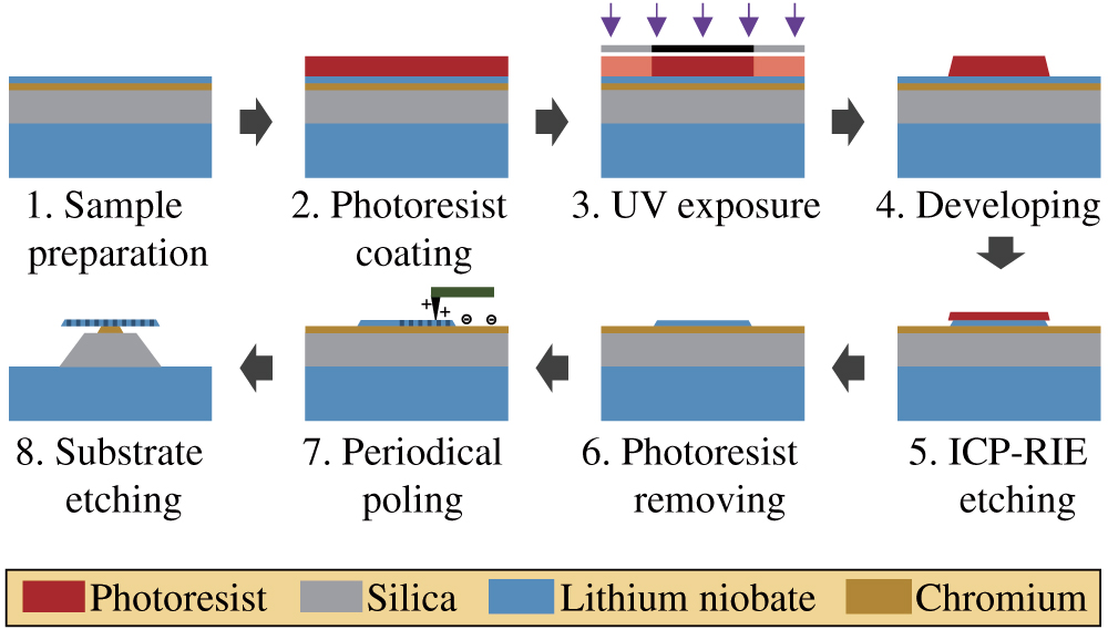
A Z-cut LN film with a thickness of 700 nm was used to fabricate PPLN microdisk resonators. A chromium layer with a thickness of 100 nm just beneath the LN film served as the bottom electrode in the polarizing process. Figure 1 indicates the fabrication process of PPLN microcavities. First, the LN film was carefully cleaned by using acetone, ethanol, and purified water. Next, a layer of photoresist with around 3 μm thickness was coated on the cleaned sample by a spin coater. Then the photoresist-coated LN film was covered by a chromium mask with cavity patterns on it and exposed to ultraviolet (UV) light, by which the patterns were transferred from the chromium mask to the photoresist after developing. In the following, the area of the LN thin film without photoresist protection was etched up by inductively coupled plasma reactive ion etching (ICP-RIE). Thus, the patterns were transferred to the LN film, forming microdisk resonators. In the meantime, the chromium layer originally beneath the LN film was exposed so as to load voltage to polarize the LN disks. After removing the residual photoresist by acetone, the LN film on the sample is precisely polished by using chemo-mechanical polishing (CMP) to eliminate the roughness of the cavity sidewall brought by dry etching. After the CMP process, the thickness of the LN film was reduced to 511.6 nm, which was measured by PFM. Then the LN microdisks were periodically poled by applying a strong electric field between the PFM probe tip and the bottom chromium electrode. Finally, the chromium and silica were partially removed to achieve a suspended PPLN microdisk for the convenience of coupling via tapered fiber.
Figure 1.Flow diagram depicting the fabrication process of the PPLN microdisk resonators.
To manifest the processing capability of our technique, we fabricated PPLN structures with a complicated domain pattern and very small unit size. As examples, the logo of Nankai University is shown in Fig. 2(a), while a strip domain pattern with only 200 nm spatial period is demonstrated in Fig. 2(b). PPLN devices with hundreds of nanometers (nm) spatial periods may find applications in mirrorless optical parametric oscillators [24], backward frequency conversions [25], and ferroelectric memories [26]. The fabrication of the PPLN domain pattern shown in Figs. 2(a) and 2(b) clearly shows that our techniques have the ability to fabricate PPLN microdevices with complicated domain pattern and submicrometer unit size. PPLN devices such as microdisks, microrings, and waveguides with large sizes could in principle be fabricated by connecting a series of polarized areas with the assistance of a moving stage having a large working distance and high precision.
Figure 2.Characteristics of a series of PPLN microdevices. (a) PFM image of the logo of Nankai University. (b) PPLN strips with 100 nm width and 100 nm distance. (c) PFM image of a PPLN microdisk without HF etching. (d) The measured factor of the PPLN microdisk. The inset represents the optical microscope image of a typical PPLN microdisk resonator. (e) Transmission spectrum of the resonator from 1540 to 1550 nm, showing the FSR of the pump mode.
Optical characterizations of the fabricated PPLN microdisk, such as domain and geometric structures, optical transmission spectrum, and quality factors, were performed, and the results are depicted in Figs. 2(c)–2(e). Figure 2(c) shows the PFM image of the PPLN microdisk before hydrofluoric acid (HF) etching. The dark areas at the edge represent the microstructures where the polarization is reversed, while the golden area in the middle of the cavity is the original state without polarization reversion. A radical domain pattern supporting narrowband spatial wave vectors, compared with strip-shaped domain structure, is clearly seen. Because the WGMs always distribute at the edge of the microdisk, the length of the periodically poled structures in the radial direction was set to be 6 μm. The domain period number of the PPLN is 126, which was designed to achieve QPM SHG using . The factor of the PPLN microdisks is depicted in Fig. 2(d), from which one sees that the factor is . The factors are mainly limited by the surface roughness (around 5 nm) as a result of the different etching rate of the and surfaces of LN in hydrofluoric acid [21]. The factor will have significant influence on the conversion efficiency of the nonlinear frequency conversion process. The roughness of the PPLN microdisk could be suppressed by protecting the microdisk from HF etching during the HF etching process to form the silica pillar. The image of the optical microscope is depicted in Fig. 2(d) as an inset, according to which one knows that there is a wedge structure at the edge of the microdisk caused by the CMP process. The central round dark area in the middle is the chromium pillar, and the next ring structure illustrates the silica pillar. Figure 2(e) shows the normalized transmission spectrum from 1540 to 1550 nm, illustrating the free-space range (FSR) of the PPLN microresonator. The mode marked as red with an FSR of 4.25 nm serves as the pump mode during the nonlinear process.
3. EXPERIMENTAL SETUP AND SHG SIGNAL
The experimental setup for nonlinear optical experiments is schematically illustrated in Fig. 3. A continuous-wave tunable narrow-bandwidth laser working in the 1550-nm band served as the pump. The pump laser was divided into two parts by an optical fiber coupler after a fiber polarization controller and an attenuator (not presented in Fig. 3). The smaller part (1%) was collected by a power meter to monitor the laser power. The major part (99%) was coupled into the PPLN disk through a tapered fiber acting as the pump in the following experiments. The PPLN disk was mounted on a three-axis piezo stage so as to accurately control its coupling with the tapered fiber. Both the generated SHG signal and the transmitted pump were extracted by the same tapered fiber. The tapered fiber was fabricated by thermal pulling, and the diameter of the waist was less than 2 μm to ensure the coupling efficiency of the SHG signal. The output from the tapered fiber was also separated into two parts: 90% of the collected light was sent to a grating spectrometer (Spectr.), whose spectral response is in the visible band, to capture the nonlinear signals in the 780 nm band, while the remaining 10% of the energy was received by a photodetector (PD) working in the telecommunication band. The electric signals from the PD were sent to an oscilloscope (Oscill.) to monitor the transmission spectrum of the pump, which can help us to estimate the coupling state. The wavelength of the pump laser could be finely tuned by an external drive with a sawtooth voltage signal generated by an arbitrary function generator (AFG). The AFG provided a trigger signal to the oscilloscope at the same time, making the transmission spectrum show stably in the oscilloscope. A lens and a Glan–Taylor polarizer, highlighted by green background in Fig. 3, were used to collect the scattering light from the microcavity and to verify the polarization state of the cavity modes involved in the nonlinear optical processes.
Figure 3.Experimental setup for nonlinear optical experiments in PPLN microdisk resonators. PM, power meter; FPC, fiber polarization controller; AFG, arbitrary function generator; PD, photodetector.
The QPM condition for the SHG in the PPLN microdisk resonators can be described as , where and represent the azimuthal quantum numbers of the pump and the signal, respectively. is the domain period number of the PPLN microdisk. When the acting WGMs satisfied the phase-matching condition, the energy conservation, and the multiple-resonance condition () simultaneously, the nonlinear signal reaches its maximum and is much easier to be detected. In experiments, a series of SHG signals were observed in the PPLN microdisk resonator. The most efficient SHG signal was obtained at the wavelength of 770.9 nm for the PPLN microdisk resonator shown in Fig. 4(a) with a pump wavelength at 1541.8 nm. This SHG and the corresponding pump are marked as red and blue in Fig. 4(a), respectively. By comparing the experimentally observed resonance wavelengths with the simulated ones, we approximately ascribed the pump and the signal WGMs to and , respectively. The mode cross sections of the pump and the signal simulated by COMSOL are depicted in the insets of Fig. 4(a). The simulated dispersion relations of the pump mode (blue) and the signal mode (red) are plotted in Fig. 4(b), according to which one can obtain the theoretical domain period number 127, which equals , which is slightly different from the practical one of 126.
Figure 4.Characteristics of the WGMs involved in the SHG process. (a) Spectra of the pump (blue) and the generated nonlinear signal (red); the insets represent the simulated optical modes of the pump and the signal. (b) Relationship between the wavelength and the azimuthal quantum number of the pump and the signal modes.
As pointed out, the QPM technique can support the conversion between two TM modes with their electric vectors parallel to the crystal axis so that the nonlinear efficient can be employed in the nonlinear conversion process. To further confirm the polarization of the WGMs related to SHG, we detected the light scattered from the PPLN microdisk near 1541.8 nm and 770.9 nm (the corresponding transmission spectra are marked in black in Fig. 5), respectively, after a Glan–Taylor polarizer. The results are shown in Fig. 5, where TE and TM indicate the scattered light polarized horizontally and vertically, respectively. When the Glan–Taylor prism was polarized vertically, a high voltage signal was generated in the PD; when the Glan–Taylor prism was polarized horizontally, a weak response was observed. Therefore, we can conclude that both the pump and the signal belong to TM modes because their corresponding electric components in the TM case are much stronger than those in the TE case as shown in Figs. 5(a) and 5(b). This means that we achieved SHG between TM modes with employed. Although some works about nonlinear optical effects in on-chip PPLN microresonators [18,21–23] have been reported, as far as we know, no devices that can use in the whole resonator have been reported.
Figure 5.Transmission (black) and scattering spectra polarized horizontally (blue) and vertically (red) for the (a) pump and (b) signal.
We also measured the conversion efficiency of the SHG signal, which is defined as . The dependence of the conversion efficiency on the pump power was measured, and the results are shown by the black squares in Fig. 6(a). Comparing the measured results with the theoretical simulation (see Appendix A), we derived a normalized conversion efficiency of . Figure 6(b) is the theoretical conversion efficiency, which is saturated at around 2.7% with a 30 W pump power. Compared to the optimized theoretical conversion efficiency approaching 100% [19], there is still a large space for further improvement. On the other hand, we theoretically calculated the conversion efficiency between TM fundamental modes in a PPLN microdisk with a quality factor of when the QPM condition is well satisfied. In this case, the theoretical normalized conversion efficiency reaches , which is 6 times larger than the one we obtained.
Figure 6.Conversion efficiency of the SHG signal in experiment and theory. (a) The conversion efficiency at low pump power detected in the experiment (black empty squares) and fitted in theory (red line). (b) Theoretical conversion efficiency showing the saturation under strong pump.
It is a pity that, despite the fact that was successfully utilized, the SHG conversion efficiency in our PPLN microdisk is still lower than that in monocrystalline LN microresonators associated with the birefringent PM condition [6,27,28]. The main reasons are listed as follows. (1) Low quality factors due to the surface roughness mainly induced by different HF etching rates for the +Z and −Z surfaces of LN crystal, which could be improved by introducing post-processing techniques such as chemico-mechanical polishing or high-temperature treatment. (2) Although the radial PPLN structure is designed for the frequency conversion between fundamental modes, the actual modes in the experiment involved in the conversion process are second-order modes due to the fabrication tolerance, leading to a lower effective nonlinear coefficient. (3) The degradation of the mode overlap between the pump and the signal caused by gradual wedge. In this situation, the modes at the 780 nm band are much closer to the edge of the cavity than the ones at the 1550 nm band [see Fig. 4(a)]. (4) The poling pattern is always unavoidably shifted with respect to the center of the fabricated microdisk. Compared with the experimental domain period number (), the theoretical domain period number (, calculated from the simulated modes and ) is a little bit larger. This will also lead to a lower effective nonlinear coefficient, as depicted in Fig. 7(b), and therefore a lower conversion efficiency compared to the one without deviation [20,29]. We believe it is possible to get a high nonlinear frequency conversion efficiency in PPLN microcavities by optimizing the fabrication process.
Figure 7.(a) Schematic draft of an eccentric poling structure, where represents the offset of the poling pattern with respect to the center of the resonator. (b) The effective nonlinear coefficient versus the period number with a chirp in the domain period, caused by a shift of the poling pattern with a 0.3 μm offset.
In summary, we reported a fabrication method to make a PPLN device on a chip by PFM-tip polarization, breaking through the limitation on the size and shape of the domain pattern obtained by applying voltage on traditional electrodes. The fabrication process of PPLN with PFM tips allows us to achieve QPM conditions between any modes we desired to ensure efficient frequency conversion. PPLN microdisk resonators with a domain spatial period of 1.98 μm and a duty ratio of 0.5 were fabricated. The quality factor of the fabricated resonators reached . The nonlinear coefficient was successfully employed in the SHG process between TM WGMs under the QPM condition in the PPLN microdisk resonator. The SHG conversion efficiency was measured to be , which has great potential to be significantly improved. The work not only paves the way for PPLN photonic devices fabrication but also shows the possibility to achieve efficient nonlinear frequency conversions in LN microresonators associated with various WGMs in the QPM regime.
APPENDIX A: THE THEORY FOR SHG IN WAVEGUIDE-COUPLED WGM RESONATORS
Coupled-mode theory is one of the classical theories to describe the coupling state between the waveguide and the microcavity. We can predict the conversion efficiency of the SHG in our system by the following coupled equations [30] similar to the quantized model [31]: where and are the complex field amplitudes of the pump and the second-harmonic signal in the cavity; represents the power amplitude of the pump mode in the waveguide; and are the intrinsic loss rates of the cavity modes associated with the pump and the signal, which include the loss induced by scattering, radiation, absorption, and so on; and are the coupling loss rates related to the waveguide extraction; and () are the resonance angular frequencies of the pump and the signal; and are the frequency detunings of the pump and the second-harmonic signal; and and are the nonlinear coupling coefficients. The nonlinear coupling coefficients are related to the modes participating in the nonlinear frequency conversion processes, which can be described as [30]
APPENDIX B: THE TRANSMISSION CHARACTERISTICS OF THE WAVEGUIDE
To describe the transmission of the waveguide coupled to the PPLN microdisk under the weak pump approximation, we used the following coupled equation without nonlinear interactions for convenience: where is the amplitude of the cavity mode, and and are coupling coefficients corresponding to the intrinsic and the coupling losses, respectively. is the frequency detuning, and is the amplitude of the pump. Thus, the transmitted amplitude through the waveguide can be expressed as According to Eqs. (B1) and (B2), one can obtain the steady-state transmission of the system: In the experiment, it is difficult to measure the values of , , , and directly. Instead, we can fit the transmission spectra of the pump and signal modes as depicted in Fig. 8 using Eq. (B3) to calculate the values of the loss rates. Figure 8(a) shows the detected transmission spectra of the pump mode around 1541.8 nm (marked in black) and the Lorentz fit with Eq. (B3). Figure 8(b) shows the transmission spectra of the signal mode around 770.9 nm (marked in black), the nonlinear fit (marked in orange), and the Lorentz fit of each single mode (the signal mode has been marked with a red solid line, while others are marked with red dashed lines).
Figure 8.Transmission spectra of the PPLN microdisk coupled with a tapered fiber and their Lorentz fits for the (a) pump and (b) signal.
In order to obtain the nonlinear coupling coefficients and , we need to know the field distributions (the azimuthal and radial quantum numbers) of the WGMs acting in the SHG processes. This work is done by comparing the calculated resonances’ wavelengths by using COMSOL software with the measured broadband transmission spectra.
Figure 9(a) demonstrates the transmission spectrum in the 1550 nm band with quantum numbers and the polarization state marked. The following parameters are used to perform the simulation for modes confirmation in the 1550 nm band: the thickness of the microdisk is 530.94 nm, the inner radius is 38.15 μm, the outer radius is 40.91 μm, and the refractive indices are and , respectively. It is worth mentioning that the polarization state of each WGM mode shown in Fig. 9(a) has been verified by checking the polarization of the scattering light. According to Fig. 9(a), we attribute the pump mode participating in the nonlinear frequency conversion processes to .
Figure 9.Transmission spectra of the used PPLN microdisk and the attributed quantum numbers for each mode in the (a) 1550 nm band and (b) 780 nm band.
Figure 9(b) shows the transmission spectrum in the 780 nm band. The geometric structures used to calculate the resonance wavelengths are the same as those for Fig. 9(a). The refractive indices of LN crystal in the 780 nm band are set to be and . The involved signal mode is assigned to . Thus, we obtained the field distribution of the pump mode and the signal mode [see Fig. 4(a)].
APPENDIX D: CONVERSION EFFICIENCY OF SHG
We estimate the conversion efficiency of the SHG by solving the coupled Eq. (A1) in the steady-state condition () numerically using the following parameters: , , , , (), , , , , , , , , , and . According to Fig. 6, the theoretically calculated conversion efficiencies agree very well with the experimental data; it shows that the normalized conversion efficiency of the SHG is , and the inferred theoretical saturated conversion efficiency of our system is around 2.7%.
[23] J. Lu, J. B. Surya, X. Liu, A. W. Bruch, Z. Gong, Y. Xu, H. X. Tang. Ultra-efficient frequency conversion in a periodically poled thin film lithium niobate microring resonator. Frontiers in Optics, FTu6B.2(2019).
[27] J. Moore, J. K. Douglas, I. W. Frank, T. A. Friedmann, R. M. Camacho, M. Eichenfield. Efficient second harmonic generation in lithium niobate on insulator. Conference on Lasers and Electro-Optics, STh3P.1(2016).