• Acta Optica Sinica
  • Vol. 43, Issue 5, 0528001 (2023)
Yu Wang1, Di Xiao3, Yangyang Niu1, Jie Yang1, Pengxi Yang1, Zhaohao Zhu1, Guolu Yin1、2、*, and Tao Zhu1、2
Author Affiliations
  • 1Key Laboratory of Optoelectronic Technology & Systems, Ministry of Education, Chongqing University, Chongqing 400044, China
  • 2State Key Laboratory of Coal Mine Disaster Dynamics and Control, Chongqing University, Chongqing 400044, China
  • 3Hunan Great Wall Hidden Optical Fiber Technology Company, LTD., Changsha 410000, Hunan, China
  • show less
    DOI: 10.3788/AOS221551 Cite this Article Set citation alerts
    Yu Wang, Di Xiao, Yangyang Niu, Jie Yang, Pengxi Yang, Zhaohao Zhu, Guolu Yin, Tao Zhu. Structural Deformation of Fiber Optic Hydrophone Probe Based on Optical Frequency Domain Reflectometry[J]. Acta Optica Sinica, 2023, 43(5): 0528001 Copy Citation Text show less
    OFDR sensing system and monitoring prototype. (a) OFDR sensing system; (b) monitoring prototype
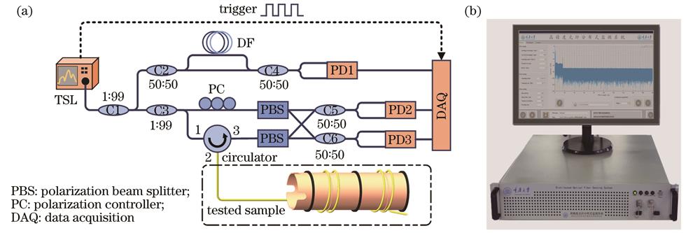
    Fig. 1. OFDR sensing system and monitoring prototype. (a) OFDR sensing system; (b) monitoring prototype
    Signal demodulation process of OFDR
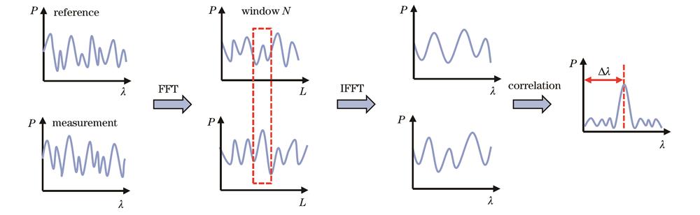
    Fig. 2. Signal demodulation process of OFDR
    Schematic diagram of hydrophone probe shape measurement
    Fig. 3. Schematic diagram of hydrophone probe shape measurement
    Experimental setup of fiber optic hydrophone probe deformation testing
    Fig. 4. Experimental setup of fiber optic hydrophone probe deformation testing
    Simulation results of deformation of fiber optic hydrophone probe. (a) Outside of probe; (b) cross section of probe
    Fig. 5. Simulation results of deformation of fiber optic hydrophone probe. (a) Outside of probe; (b) cross section of probe
    Wavelength shift caused by deformation of fiber optic hydrophone probe under different pressures. (a) Hydrophone probe 1 covered with soft rubber; (b) hydrophone probe 2 encapsulated by metal skeleton
    Fig. 6. Wavelength shift caused by deformation of fiber optic hydrophone probe under different pressures. (a) Hydrophone probe 1 covered with soft rubber; (b) hydrophone probe 2 encapsulated by metal skeleton
    Constriction radius of fiber optic hydrophone probe and wavelength shift varying with pressure. (a) Hydrophone probe 1 covered with soft rubber; (b) hydrophone probe 2 encapsulated by metal skeleton
    Fig. 7. Constriction radius of fiber optic hydrophone probe and wavelength shift varying with pressure. (a) Hydrophone probe 1 covered with soft rubber; (b) hydrophone probe 2 encapsulated by metal skeleton
    Wavelength shift of fiber optic hydrophone probe 1 at pressure of 6 Mpa
    Fig. 8. Wavelength shift of fiber optic hydrophone probe 1 at pressure of 6 Mpa
    Reconstruction results of cross-sectional deformation of fiber optic hydrophone probes under different static pressures. (a) Hydrophone probe 1 covered with soft rubber; (b) hydrophone probe 2 encapsulated by metal skeleton
    Fig. 9. Reconstruction results of cross-sectional deformation of fiber optic hydrophone probes under different static pressures. (a) Hydrophone probe 1 covered with soft rubber; (b) hydrophone probe 2 encapsulated by metal skeleton
    Reconstruction result of cross-sectional deformation of fiber optic hydrophone probes under static pressure of 6 MPa
    Fig. 10. Reconstruction result of cross-sectional deformation of fiber optic hydrophone probes under static pressure of 6 MPa
    Yu Wang, Di Xiao, Yangyang Niu, Jie Yang, Pengxi Yang, Zhaohao Zhu, Guolu Yin, Tao Zhu. Structural Deformation of Fiber Optic Hydrophone Probe Based on Optical Frequency Domain Reflectometry[J]. Acta Optica Sinica, 2023, 43(5): 0528001
    Download Citation