• Photonics Research
  • Vol. 3, Issue 4, 158 (2015)
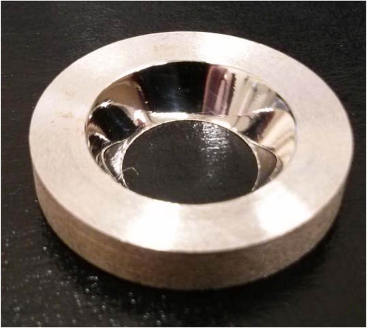
James Leibold and Ribal Georges Sabat*
Author Affiliations
  • Department of Physics, Royal Military College of Canada, PO Box 17000, STN Forces, Kingston, Ontario K7K7B4, Canada
  • show less
    DOI: 10.1364/PRJ.3.000158 Cite this Article Set citation alerts
    James Leibold, Ribal Georges Sabat. Laser-induced controllable chirped-pitch circular surface-relief diffraction gratings on AZO glass[J]. Photonics Research, 2015, 3(4): 158 Copy Citation Text show less
    CDG.
    Fig. 1. CDG.
    Schematic demonstrating the optical geometry of the cross-section of a CDG.
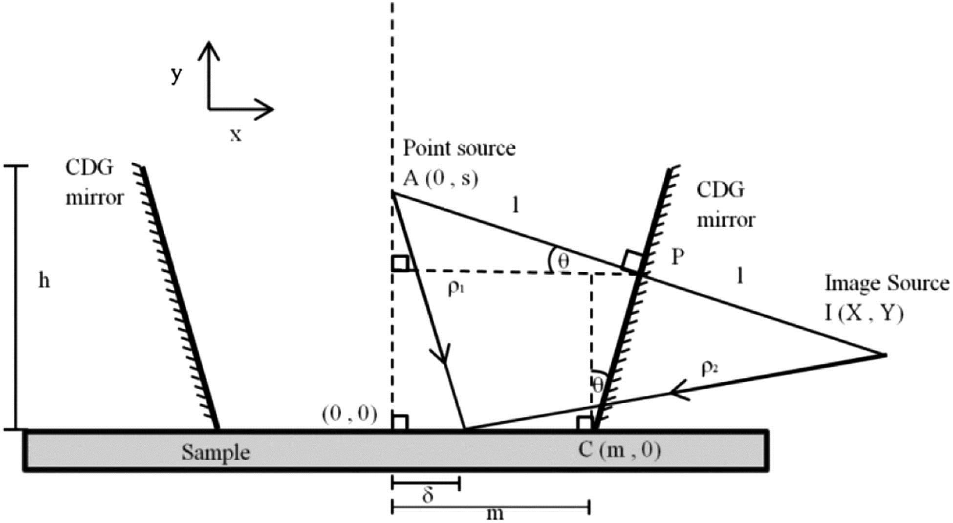
    Fig. 2. Schematic demonstrating the optical geometry of the cross-section of a CDG.
    Experimental setup for writing concentric chirped gratings using a CDG. a) If the point source is on the left sample film, then s is positive and the inscribing light is divergent. b) If a lens with a longer focal length is used to place the image of the point source on right of the CDG, then s is negative and the light is convergent.
    Fig. 3. Experimental setup for writing concentric chirped gratings using a CDG. a) If the point source is on the left sample film, then s is positive and the inscribing light is divergent. b) If a lens with a longer focal length is used to place the image of the point source on right of the CDG, then s is negative and the light is convergent.
    Real-time diffraction efficiency of a chirped circular SRG as it is being inscribed in AZO glass. The inscribing laser with a measured irradiance of 1209 mW/cm2 was turned on shortly after the 0 s mark and turned off after 700 s of exposure time. The small dip in diffraction efficiency after 700 s can be attributed to the turning off of the inscribing laser. It is possible that the subsequent rise in diffraction efficiency can be attributed to the relaxation of the AZO glass material after the inscribing laser was turned off.
    Fig. 4. Real-time diffraction efficiency of a chirped circular SRG as it is being inscribed in AZO glass. The inscribing laser with a measured irradiance of 1209mW/cm2 was turned on shortly after the 0 s mark and turned off after 700 s of exposure time. The small dip in diffraction efficiency after 700 s can be attributed to the turning off of the inscribing laser. It is possible that the subsequent rise in diffraction efficiency can be attributed to the relaxation of the AZO glass material after the inscribing laser was turned off.
    AFM imagery at 1 mm from the edge of a circular SRG inscribed using a 28.9° CDG with a point source of inscribing light at s=−10 cm.
    Fig. 5. AFM imagery at 1 mm from the edge of a circular SRG inscribed using a 28.9° CDG with a point source of inscribing light at s=10cm.
    Theory and measurements for a circular SRG inscribed from a 28.9° CDG with diverging point source 3 cm away from sample.
    Fig. 6. Theory and measurements for a circular SRG inscribed from a 28.9° CDG with diverging point source 3 cm away from sample.
    Theory and measurements for a circular SRG inscribed from a 28.9° CDG with diverging point source 6 cm away from sample.
    Fig. 7. Theory and measurements for a circular SRG inscribed from a 28.9° CDG with diverging point source 6 cm away from sample.
    Theory and measurements for a circular SRG inscribed from a 28.9° CDG with diverging point source 9 cm away from sample.
    Fig. 8. Theory and measurements for a circular SRG inscribed from a 28.9° CDG with diverging point source 9 cm away from sample.
    Theory and measurements for a circular SRG inscribed from a 28.9° CDG with converging point source -10 cm away from sample. AFM measurements are not made for the values of δ smaller than 4 mm because the height h of the CDG prohibits the formation of grating lines in the center of the SRG, as discussed in Section 4.
    Fig. 9. Theory and measurements for a circular SRG inscribed from a 28.9° CDG with converging point source -10 cm away from sample. AFM measurements are not made for the values of δ smaller than 4 mm because the height h of the CDG prohibits the formation of grating lines in the center of the SRG, as discussed in Section 4.
    Theory and measurements for a circular SRG inscribed from a 28.9° CDG with converging point source −20 cm away from sample. AFM measurements are not made for the values of δ smaller than 3 mm because the height h of the CDG prohibits the formation of grating lines in the center of the SRG, as discussed in Section 4.
    Fig. 10. Theory and measurements for a circular SRG inscribed from a 28.9° CDG with converging point source 20cm away from sample. AFM measurements are not made for the values of δ smaller than 3 mm because the height h of the CDG prohibits the formation of grating lines in the center of the SRG, as discussed in Section 4.
    Dependence of grating pitch on distance from the center for 14 simulated circular SRGs inscribed with a 28.9° CDG using different distances to the point source of light s with a wavelength of 532 nm. A positive value of s denotes a divergent source while a negative value indicates a convergent source. As the distance to the point source increases, whether positive or negative, the slope of the grating approaches zero. Small absolute values of s result in steeper slopes and nonlinear curves. The grating pitch can be further controlled by changing the CDG angle θ or the wavelength of light λ. Curves are derived from a ray-trace computer simulation discussed in Section 2.
    Fig. 11. Dependence of grating pitch on distance from the center for 14 simulated circular SRGs inscribed with a 28.9° CDG using different distances to the point source of light s with a wavelength of 532 nm. A positive value of s denotes a divergent source while a negative value indicates a convergent source. As the distance to the point source increases, whether positive or negative, the slope of the grating approaches zero. Small absolute values of s result in steeper slopes and nonlinear curves. The grating pitch can be further controlled by changing the CDG angle θ or the wavelength of light λ. Curves are derived from a ray-trace computer simulation discussed in Section 2.
    James Leibold, Ribal Georges Sabat. Laser-induced controllable chirped-pitch circular surface-relief diffraction gratings on AZO glass[J]. Photonics Research, 2015, 3(4): 158
    Download Citation