Abstract
Chirped-pitch nanoscale circular surface-relief diffraction gratings were photoinscribed on thin films of a Disperse Red 1 functionalized material using a holographic technique. A truncated conical mirror splits and redirects a converging or diverging laser beam, resulting in an interference pattern of concentric circles with a chirped pitch that can be controlled by varying the wavefront curvature. The resulting circular gratings have a diameter of 12mm and have the advantage of being produced in a fast, single-step procedure with no requirement for a master grating, photomask, or milling equipment.1. INTRODUCTION
Chirped linear surface-relief diffraction gratings (SRGs) are useful in a variety of applications such as spectral filters [1] and light focalizers into waveguides [2]. Chirped circular SRGs can serve similar functions as their one-dimensional linear counterparts, but have the advantage of acting in two dimensions. This allows for the design of a wide variety of diffractive optical elements, such as diffractive lenses or kinoforms [3], specialized lensacons [4], and hybrid lenses [5]. Other possible applications for circular SRGs include surface-emitting distributed feedback lasers [6], surface plasmon enhanced optical sensors [7], and the miniaturization of instruments such as spectroscopes [8].
A literature review revealed a wide range of techniques to manufacture chirped circular SRGs. Photolithography is a common microfabrication technique which uses a photomask or interference pattern to project light onto a photoresist material. This is normally a multistep process that involves coating the material with a photoresist, exposing it to a source of patterned light, etching it, and then cleaning it. In one paper, a circular SRG was generated using a linear grating pattern on a wedge-shaped mask that was rotated at a certain step interval and exposed to create a circular grating [7].
Direct milling techniques such as diamond turning [5], focused ion beams [8], or electron beam milling [9] have been used to create circular gratings onto a mold, masking material, or directly onto a desired substrate. These techniques are capable of nanometer-scale resolutions; however, they generally have a low throughput since each line of the grating is machined one at a time.
Sign up for Photonics Research TOC. Get the latest issue of Photonics Research delivered right to you!Sign up now
Furthermore, soft lithography uses a flexible mold to transfer a surface-relief pattern onto a desired substrate [10]. The resulting patterns can further be modified by mechanically bending, compressing, or stretching the mold [11]. Although this technique is good for mass production, it relies on the fabrication of the original mold pattern through either a direct milling or a photolithography technique, as previously described.
In this paper, we use a three-dimensional laser beam splitting technique with a custom-built fixture called a circular diffraction grating generator (CDG), pictured in Fig. 1, to inscribe large-scale, chirped-pitch circular diffraction gratings using a single-step process. An incident laser beam on the CDG is simultaneously split and redirected to form an interference pattern of concentric circles of laser light inside the aperture. This pattern is then photoinscribed onto an exposed AZO glass thin film by means of the photomechanical behavior of the AZO glass molecules. This occurs due to the trans-cis photochemical isomerization of the azobenzene chromophores [12]. Herein, we also present a theory that was successfully fitted to experimental results, which enables understanding of how the pitch variations within each circular grating can be controlled with the geometry of the CDG, the wavelength of the inscribing light, and the curvature of the laser wavefront.
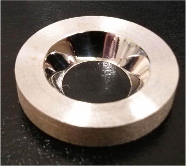
Figure 1.CDG.
Other researchers have reported the generation of circular SRGs in azobenzene-functionalized materials using optical sources such as a Bessel beam [13] or interference patterns from the end of an optical fiber [14]. The method introduced in this paper has several advantages over other techniques in that the size of the circular SRG produced is scalable and the pitch and chirp of the grating are controllable within the limitations of the theory.
2. THEORY
Assume a mirror in the shape of a hollow truncated cone. The inner surface of this shape is reflective and is the basis for a theoretical CDG. When a point source of light is positioned on the axis of symmetry of the CDG at some distance , the spherical wavefront will be reflected by the mirrored surface towards the smaller aperture end of the CDG. This reflected light will interfere with the directly incident light, creating a pattern of concentric rings with sinusoidal intensity variations.
A schematic of the cross-section of the CDG and a point source is shown in Fig. 2. The mirrored surface of the CDG will create a reflected image at the coordinates . A geometric analysis of the diagram results in the expression where is the angle between the mirrored surface and the normal of the sample and is the length of the line normal to the mirror to the point source. The variable can be expressed in terms of the CDG mirror angle , , and minor radius , giving . Substituting this equation into Eq. (1) and simplifying using trigonometric identities gives the equations
At a given distance from the center of the sample, the optical path difference (OPD) between the two rays of light that strike that location can be given by

Figure 2.Schematic demonstrating the optical geometry of the cross-section of a CDG.
In order to find the grating spacing at a particular distance from the center , the change in the phase difference between paths and at the point and must be . By a similar argument, the change in OPD must be equal to one wavelength of the inscribing light , giving
Substituting Eq. (2) into (3) and then Eq. (3) into (4) yields a result that is very complicated to isolate for the variable . For this reason, a ray-tracing computer simulation was used to generate graphs of the grating pitch versus distance using the given experimental parameters , , , , as well as the height of the CDG, . It is also possible to achieve a numerical approximation of in terms of from Eq. (4) for a given set of parameters by using commercially available algebraic math software. This was done to independently verify the accuracy of the ray-tracing simulation, proving that the results of both methods are, for all practical purposes, equivalent.
3. EXPERIMENT
A CDG fixture was machined and polished using manual equipment found in common machine shops. Care was taken to ensure that the reflecting conical surface was a true truncated cone, finishing at a knife-edge on the minor aperture, with its central axis perpendicular to the flat face. The material used was high-quality annealed carbon steel. After machining, the CDG fixture was washed with solvent and dried with air. Approximately 500 nm of silver was then sputter-coated onto the CDG in order to create a mirrorlike finish. The CDG dimensions were measured using a digital caliper and an analog traveling microscope. It was found to have an angle of and a small aperture radius of 5.95 mm.
Dispersed Red 1 AZO glass was synthesized according to [15]. Solutions of AZO glass were then prepared from powder by mixing with dichloromethane at a 3% concentration by weight. The solution was subsequently mechanically shaken and filtered with a 50 μm filter. Solid films were fabricated by spin-casting the solution onto cleaned and dried microscope slides. At a rate of 1500 rpm, the solid films had a thickness of approximately 400 nm, as measured with a profilometer.
An AZO glass sample was placed against the small aperture face of the CDG. The beam from a Verdi diode-pumped laser, at a wavelength of 532 nm, was passed through a spatial filter, collimated, and circularly polarized by a quarter-wave plate. The resulting collimated beam had an irradiance of . The beam diameter was controlled by a variable iris and was passed through a spherical convex lens with a known focal length to create a point source image, as seen in Fig. 3. This point source was placed at a known distance from the sample and was used to inscribe the concentric interference pattern directly onto the AZO glass films with an exposure time of 450 seconds. This was repeated four more times to create SRGs from distances of 3, 6, 9, , and .
Figure 3.Experimental setup for writing concentric chirped gratings using a CDG. a) If the point source is on the left sample film, then is positive and the inscribing light is divergent. b) If a lens with a longer focal length is used to place the image of the point source on right of the CDG, then is negative and the light is convergent.
Real-time diffraction efficiency measurements for the first-order diffraction were taken as a circular SRG was being written. This was accomplished by shining a 405 nm wavelength probe laser onto the sample as the SRG was being inscribed. The probe laser was incident on a small part of the grating and light was diffracted along an arc of a circle. The probe laser was mechanically chopped and the first-order diffraction arc of a circle was incident on a photodiode. The signal from the photodiode was then fed through a lock-in amplifier and recorded on a computer. The diffraction efficiency in percent was calculated by dividing the first-order diffraction signal by the signal from the directly incident beam and multiplied by 100.
4. RESULTS
Figure 4 shows the real-time diffraction efficiency of a chirped pitch circular SRG as it was being inscribed using a CDG. Care was taken to place the photodetector close to the sample in order to collect as much light as possible from the first diffraction order mode, but loss of light outside the area of the detector may have resulted in a slight underestimation of the diffraction efficiency. The maximum observed diffraction efficiency was observed to be 4% after a 700 s exposure, with an inscribing laser irradiance of .
Figure 4.Real-time diffraction efficiency of a chirped circular SRG as it is being inscribed in AZO glass. The inscribing laser with a measured irradiance of was turned on shortly after the 0 s mark and turned off after 700 s of exposure time. The small dip in diffraction efficiency after 700 s can be attributed to the turning off of the inscribing laser. It is possible that the subsequent rise in diffraction efficiency can be attributed to the relaxation of the AZO glass material after the inscribing laser was turned off.
Atomic Force Microscope (AFM) measurements of the grating pitches were taken using a Pacific Nanotechnology Nano-R O-020-0002 scanning probe microscope. The AFM was calibrated using a sample with known dimensions, and has a measurement accuracy of 2%. The distance between grating peaks was measured at intervals of 0.5 mm, starting from the outside edge of the circular SRGs. Each measurement was taken a second time from the opposite side of the circular SRGs, and the two measurements were averaged. An example of the AFM imagery can be seen in Fig. 5. Although a profile depth of 0.09 μm is quite shallow, the depth and diffraction efficiency of the circular grating can be increased with a combination of stronger irradiance and longer exposure time, as demonstrated in Fig. 4.
Figure 5.AFM imagery at 1 mm from the edge of a circular SRG inscribed using a 28.9° CDG with a point source of inscribing light at .
The resulting graphs of the grating pitch as a function of distance from the center of the circular grating are illustrated in Figs. 6–10. The lines in these graphs show the results of the computer simulation for a CDG with , as well as two additional lines at to illustrate the range of error from the physical measurements of the CDG angle. The hollow circle points represent data taken from the numeric solution from algebraic computer software to verify the fidelity of the ray-trace simulation. The black squares with error bars are physical measurements of the grating pitch from the AFM.
The measurement data largely agree with the predicted theoretical pitches for all tested values of . All five graphs in Figs. 6–10 show the common feature that the pitch is slightly higher than predicted near the outside edge of the SRG. It is believed that this observation is the result of the manufacturing process of the CDG. The interior radius of the CDG is finished to a knife-edge, however, and because the material supporting this area is very thin, it is susceptible to deformation during the polishing process. This results in a slight decrease in the effective CDG angle near the interior radius, effectively increasing the grating pitch at the edge of the resulting SRGs.
Figure 6.Theory and measurements for a circular SRG inscribed from a 28.9° CDG with diverging point source 3 cm away from sample.
Figure 7.Theory and measurements for a circular SRG inscribed from a 28.9° CDG with diverging point source 6 cm away from sample.
Figure 8.Theory and measurements for a circular SRG inscribed from a 28.9° CDG with diverging point source 9 cm away from sample.
Figure 9.Theory and measurements for a circular SRG inscribed from a 28.9° CDG with converging point source -10 cm away from sample. AFM measurements are not made for the values of smaller than 4 mm because the height of the CDG prohibits the formation of grating lines in the center of the SRG, as discussed in Section 4.
Figure 10.Theory and measurements for a circular SRG inscribed from a 28.9° CDG with converging point source away from sample. AFM measurements are not made for the values of smaller than 3 mm because the height of the CDG prohibits the formation of grating lines in the center of the SRG, as discussed in Section 4.
The accuracy of the resulting interfering wavefronts, and therefore the quality of the resulting circular SRGs, is entirely dependent on the quality and alignment of the optical elements used in the experimental setup. The prototype CDG was the only optical element that was manufactured in-house. Quantitative measurements of the optical performance of this mirrored fixture are not known; however, the results in Figs. 6–10 demonstrate the sensitivity of the resulting grating pitch when the angle of the CDG mirror is altered by 1° or more. Improvements in the manufacturing process of the CDGs could help reduce this potential source of error. Alternately, it may also be possible to intentionally introduce a curve to the CDG mirror surface in the radial direction as an additional method of controlling the rate of chirp in the resulting circular SRGs.
Once the ray-trace computer simulations were validated through physical data measurements, a larger range of values of were simulated to demonstrate the range of pitches and degree of chirping that are theoretically possible. Figure 11 shows the simulated grating pitch dependence on the distance from the center of the SRG for a range from to . When the distance from the point source of light to the CDG and sample is large, the radius of curvature in the spherical wavefront of inscribing light is similarly large. In these cases, the model approaches a constant-pitch circular SRG as generated by a collimated light source, as depicted in Fig. 10 for the lines for and . When the distance to the point source of inscribing light is decreased, the degree of chirping in the grating becomes more pronounced, as seen by the increase in positive slope for with a negative value and decrease in negative slope for with a positive value.
Figure 11.Dependence of grating pitch on distance from the center for 14 simulated circular SRGs inscribed with a 28.9° CDG using different distances to the point source of light with a wavelength of 532 nm. A positive value of denotes a divergent source while a negative value indicates a convergent source. As the distance to the point source increases, whether positive or negative, the slope of the grating approaches zero. Small absolute values of result in steeper slopes and nonlinear curves. The grating pitch can be further controlled by changing the CDG angle or the wavelength of light . Curves are derived from a ray-trace computer simulation discussed in Section 2.
When running the simulation for different values of , it became apparent that the results are very sensitive to selecting the proper height of the CDG . There exists a critical value for the CDG height for optimum circular SRG inscription. If is larger than , the interference pattern will cross over the center line of the SRG, destroying the SRG in that area. Conversely, no grating is formed in the center of the SRG if is smaller than because the interference pattern does not reach the center. For a planar wave inscription, the value of can be readily obtained from geometry:
For a divergent or convergent source, the equation for the critical height of the CDG is given by
For large distances , Eq. (6) converges to Eq. (5). In Figs. 9 and 10, the AFM was unable to detect grating structures near the center of the SRG written at and . This is because the height of this particular CDG was insufficient to reach the center at a configuration with a small negative distance to the point source. For the cases where the CDG would have been too tall, the variable iris illustrated in Fig. 3 was closed so that less of the CDG was illuminated, reducing the effective height of the CDG exposed to light. This illustrates a capability of adjusting not only the pitch of the gratings, but their geometrical form.
5. CONCLUSION
Five circular SRGs were photoinscribed onto AZO glass films using a 28.9° CDG and a point source of either converging or diverging laser light at various distances from the film. The resulting grating pitches were measured as a function of distance from the center of the grating, and had a controllable chirped pitch in agreement with the theoretical predictions.
A ray-trace simulation confirmed that the chirped-pitch slope is dependent on the value , which is the distance from the sample to the point source along the optical axis. The grating pitches and the SRG diameters can further be controlled by varying the CDG geometry with parameters such as , , and the wavelength of the light source . The simulation demonstrated that chirped-pitch slopes from to 34.1 nm/mm are possible and that a slope of zero corresponds to a constant-pitch grating generated by a distant point source.
The chirped-pitch circular SRGs generated by this method were found to be sensitive to imperfections in the CDG manufacturing process as well as the overall height of the CDG. This is especially true for small values of where the geometry amplifies the sensitivity of the control parameters. For this reason, special care must be taken in the selection of dimensions of the CDG in order to ensure that circular SRGs are generated with predictable pitches.
Despite the somewhat complex nature of the optical ray path geometry of this experiment, relatively large-scale chirped circular SRGs could be designed and easily manufactured using a simple and inexpensive reflective fixture such as the CDG. This is done in a single-step process without the need for specialized lithography or milling equipment. The circular chirped SRGs were manufactured fairly quickly, on the order of 450 s with a laser irradiance of . The circular SRGs generated in this experiment had a diameter of 12 mm, but the size of the SRGs that this technique can produce is theoretically limited only by the size and power of the collimated laser beam as well as suitably sized focusing lens and CDG. It should therefore be possible, using the method described here, to generate circular SRGs with much larger diameters but equally fine subwavelength resolutions. Because of the ease, speed, and economy of this new production method, it may be possible for other researchers to have access to customized circular SRGs to meet their own application-specific research in the field of photonics.
References
[1] J. B. Shellan, C. S. Hong, A. Yariv. Theory of chirped gratings in broad band filters. Opt. Commun., 23, 398-400(1977).
[2] A. Katzir, A. C. Livanos, J. Shellan, A. Yariv. Chirped gratings in integrated optics. IEEE J. Quantum Electron., 13, 296-304(1977).
[3] D. A. Buralli, G. M. Morris, J. R. Rogers. Optical performance of holographic kinoforms. Appl. Opt., 28, 976-983(1989).
[4] S. N. Khonina, A. V. Ustinov, S. G. Volotovsky. Fractional axicon as a new type of diffractive optical element with conical focal region. Precis. Instrum. Mechanol., 2, 132-143(2013).
[5] P. He, F. Wang, L. Li, K. Georgiadis, O. Dambon, F. Klocke, A. Yi. Development of a low cost high precision fabrication process for glass hybrid aspherical diffractive lenses. J. Opt., 13, 085703(2011).
[6] C. Olson, D. G. Hall. Azimuthal mode discrimination in radially chirped concentric-circle-grating distributed feedback lasers. IEEE J. Quantum Electron., 36, 1016-1025(2000).
[7] K. Toma, M. Vala, P. Adam, J. Homola, W. Knoll, J. Dostálek. Compact surface plasmon-enhanced fluorescence biochip. Opt. Express, 21, 10121-10132(2013).
[8] Y. Park, S. H. Choi. Miniaturization of optical spectroscopes into Fresnel microspectrometers. J. Nanophoton., 7, 077599(2013).
[9] O. Barlev, M. A. Golub. Resonance domain surface relief diffractive lens for the visible spectral region. Appl. Opt., 52, 1531-1540(2013).
[10] C. Yang, K. Shi, P. Edwards, Z. Liu. Demonstration of a PDMS based hybrid grating and Fresnel lens (G-Fresnel) device. Opt. Express, 18, 23529-23534(2010).
[11] Y. Xia, E. Kim, X. M. Zhao, J. A. Rogers, M. Prentiss, G. M. Whitesides. Complex optical surfaces formed by replica molding against elastomeric masters. Science, 273, 347-349(1996).
[12] A. Priimagi, A. Shevchenko. Azopolymer-based micro- and nanopatterning for photonic applications. J. Polym. Sci. B, 52, 163-182(2014).
[13] T. Grosjean, D. Courjon. Photopolymers as vectorial sensors of the electric field. Opt. Express, 14, 2203-2210(2006).
[14] J. K. Kim, Y. Jung, B. H. Lee, K. Oh, C. Chun, D. Kim. Optical phase-front inscription over optical fiber end for flexible control of beam propagation and beam pattern in free space. Opt. Fiber Technol., 13, 240-245(2007).
[15] R. Kirby, R. G. Sabat, J. Nunzi, O. Lebel. Disperse and disordered: a mexylaminotriazine-substituted azobenzene derivative with superior glass and surface relief grating formation. J. Mater. Chem. C, 2, 841-847(2014).


