• Laser & Optoelectronics Progress
  • Vol. 55, Issue 6, 060801 (2018)
Ying Chang1、1; and Shiling Wang2、2;
Author Affiliations
  • 1 Department of Optical Engineering, Changchun University of Science and Technology, Changchun, Jilin 130022, China
  • 2 State Key Laboratory of Precision Measuring Technology and Instruments, Tianjin University, Tianjin 300072, China
  • show less
    DOI: 10.3788/LOP55.060801 Cite this Article Set citation alerts
    Ying Chang, Shiling Wang. Gaussian Beam Shaping of Round Spot Based on Spheric-Aspheric Cylindrical Lens[J]. Laser & Optoelectronics Progress, 2018, 55(6): 060801 Copy Citation Text show less
    Flow chart of the design
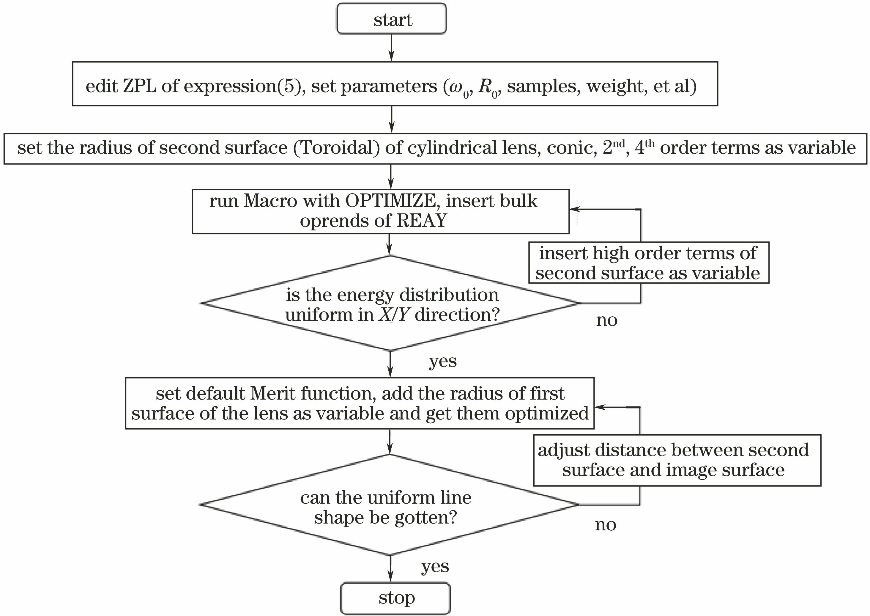
    Fig. 1. Flow chart of the design
    3D layout of spheric-aspheric cylindrical lens design. (a) System structure in sagittal plane; (b) system structure in tangential plane
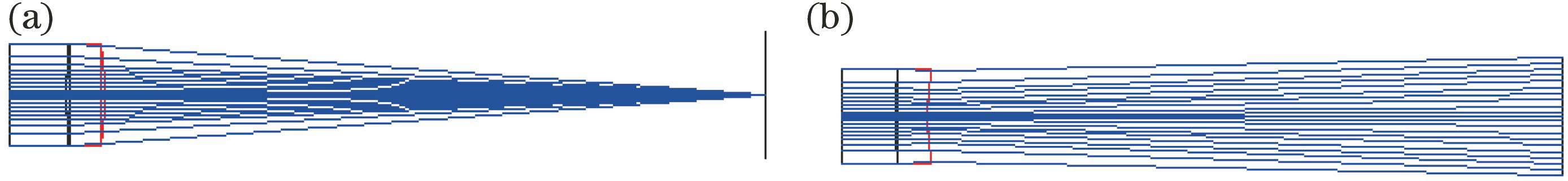
    Fig. 2. 3D layout of spheric-aspheric cylindrical lens design. (a) System structure in sagittal plane; (b) system structure in tangential plane
    Relative illumination in Y-scan and spot diam. (a) Diagram of relative illumination in Y-scan; (b) spot diagram of the system
    Fig. 3. Relative illumination in Y-scan and spot diam. (a) Diagram of relative illumination in Y-scan; (b) spot diagram of the system
    Schematic diagram of system. (a) X direction; (b) Y direction
    Fig. 4. Schematic diagram of system. (a) X direction; (b) Y direction
    3D layout of aspheric lens-cylindrical lens system. (a) X direction; (b) Y direction
    Fig. 5. 3D layout of aspheric lens-cylindrical lens system. (a) X direction; (b) Y direction
    Spot diagram of two systems. (a) Spot diagram of aspheric lens-cylindrical lens system; (b) spot diagram of spheric-aspheric cylindrical lens system; (c) line spot with different distances between image surface and last surface of cylindrical lens
    Fig. 6. Spot diagram of two systems. (a) Spot diagram of aspheric lens-cylindrical lens system; (b) spot diagram of spheric-aspheric cylindrical lens system; (c) line spot with different distances between image surface and last surface of cylindrical lens
    Relative illumination diagram of two systems
    Fig. 7. Relative illumination diagram of two systems
    Relative illumination of aspheric cylindrical lens
    Fig. 8. Relative illumination of aspheric cylindrical lens
    ParameterValue
    Wavelength range1.26-1.36 μm
    Entrance pupil diameter D8.6 mm
    R05.3 mm
    ω03.9 mm
    Line width≤200 μm
    Distance between last surfaceand image surface≤60 mm
    Table 1. Parameters of cylindrical lens design
    Ying Chang, Shiling Wang. Gaussian Beam Shaping of Round Spot Based on Spheric-Aspheric Cylindrical Lens[J]. Laser & Optoelectronics Progress, 2018, 55(6): 060801
    Download Citation