• Acta Optica Sinica
  • Vol. 39, Issue 1, 0126013 (2019)
Jian Wang1、2、*, Jun Liu1、2, and Yifan Zhao1、2
Author Affiliations
  • 1 Wuhan National Laboratory for Optoelectronics, Huazhong University of Science and Technology, Wuhan, Hubei 430074, China
  • 2 School of Optical and Electronic Information, Huazhong University of Science and Technology, Wuhan, Hubei 430074, China
  • show less
    DOI: 10.3788/AOS201939.0126013 Cite this Article Set citation alerts
    Jian Wang, Jun Liu, Yifan Zhao. Research Progress of Structured Light Coding/Decoding Communications[J]. Acta Optica Sinica, 2019, 39(1): 0126013 Copy Citation Text show less
    Schematic illustration of physical dimension resources of photons (wavelength/frequency, time, complex amplitude, polarization, space domain) and manipulating the space domain of lightwaves for structured light field (spatial amplitude, spatial phase, spatial polarization) and space array (spatial position)
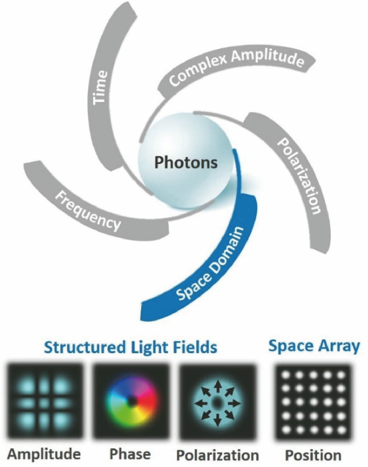
    Fig. 1. Schematic illustration of physical dimension resources of photons (wavelength/frequency, time, complex amplitude, polarization, space domain) and manipulating the space domain of lightwaves for structured light field (spatial amplitude, spatial phase, spatial polarization) and space array (spatial position)
    A summary of structured light generation methods
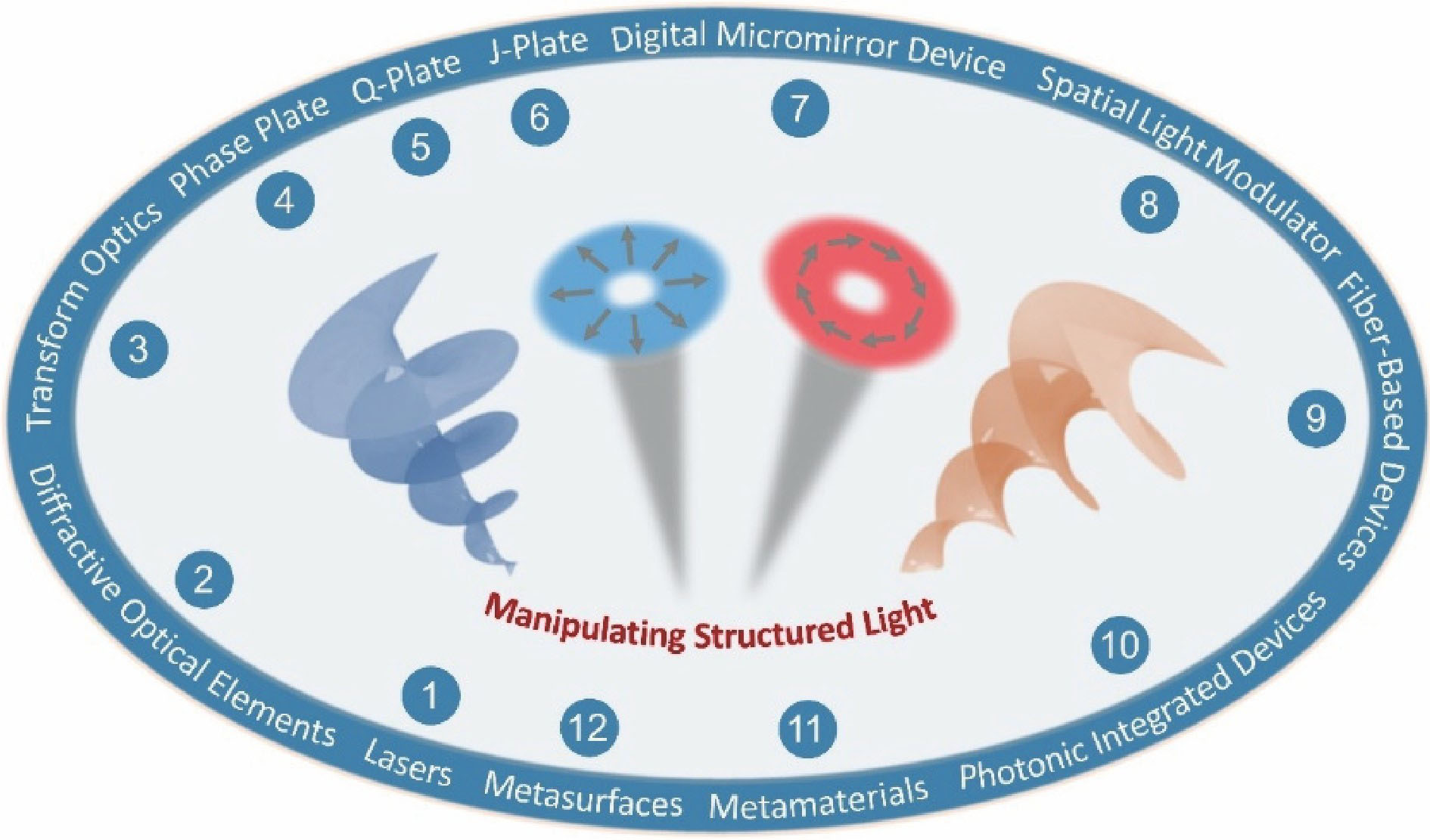
    Fig. 2. A summary of structured light generation methods
    Schematic illustration of structured light coding/decoding communications. (a) OAM mode coding/decoding communications; (b) vector mode coding/decoding communications
    Fig. 3. Schematic illustration of structured light coding/decoding communications. (a) OAM mode coding/decoding communications; (b) vector mode coding/decoding communications
    Classification of structured light coding/decoding communications
    Fig. 4. Classification of structured light coding/decoding communications
    Experimental setup for free-space OAM coding/decoding communications[109]
    Fig. 5. Experimental setup for free-space OAM coding/decoding communications[109]
    Experimental results for free-space OAM coding/decoding communications[109]
    Fig. 6. Experimental results for free-space OAM coding/decoding communications[109]
    Concept and principle diagram of free-space m-ary coding/decoding communications using Bessel beams[113]
    Fig. 7. Concept and principle diagram of free-space m-ary coding/decoding communications using Bessel beams[113]
    Measured results for free-space m-ary coding/decoding communications using Bessel beams without obstruction[113]. (a) Coding for hexadecimal numbers with 16 Bessel beams (Δ?=2); (b) intensity profiles of decoded Bessel beams of ?=-7 (hexadecimal number 4), ?=-1 (hexadecimal number 7), and ?=15 (hexadecimal number 15)
    Fig. 8. Measured results for free-space m-ary coding/decoding communications using Bessel beams without obstruction[113]. (a) Coding for hexadecimal numbers with 16 Bessel beams (Δ?=2); (b) intensity profiles of decoded Bessel beams of ?=-7 (hexadecimal number 4), ?=-1 (hexadecimal number 7), and ?=15 (hexadecimal number 15)
    Measured results for free-space m-ary coding/decoding communications using Bessel beams under different conditions[113]. (a) With obstruction; (b) with deviated obstruction
    Fig. 9. Measured results for free-space m-ary coding/decoding communications using Bessel beams under different conditions[113]. (a) With obstruction; (b) with deviated obstruction
    Experimental bit-error rate for hexadecimal and 32-ary coding/decoding communications using Bessel beams without obstruction, with deviated obstruction, and with obstruction, respectively[113]
    Fig. 10. Experimental bit-error rate for hexadecimal and 32-ary coding/decoding communications using Bessel beams without obstruction, with deviated obstruction, and with obstruction, respectively[113]
    Concept and principle diagrams of (a) high-speed mode coding/decoding communications and (b) mode hopping communications based on OAM modes[114]
    Fig. 11. Concept and principle diagrams of (a) high-speed mode coding/decoding communications and (b) mode hopping communications based on OAM modes[114]
    Experimental setup for high-speed OAM mode coding/decoding communications and OAM mode hopping communications[114]. (a) Schematic of setup; (b) intensity profiles and interferograms of OAM modes; (c) offline digital signal processing for data recovery
    Fig. 12. Experimental setup for high-speed OAM mode coding/decoding communications and OAM mode hopping communications[114]. (a) Schematic of setup; (b) intensity profiles and interferograms of OAM modes; (c) offline digital signal processing for data recovery
    Experimental results for high-speed OAM mode coding/decoding communications (20 Gbit·s-1)[114]. (a) Normalized waveforms at the output of the optical switch; (b) eye diagrams at the output of the optical switch; (c) received normalized waveforms when using the OAM mode set {-3, -1, +1, +3}; (d) received normalized waveforms when using the OAM mode set {0, 1, 2, 3}
    Fig. 13. Experimental results for high-speed OAM mode coding/decoding communications (20 Gbit·s-1)[114]. (a) Normalized waveforms at the output of the optical switch; (b) eye diagrams at the output of the optical switch; (c) received normalized waveforms when using the OAM mode set {-3, -1, +1, +3}; (d) received normalized waveforms when using the OAM mode set {0, 1, 2, 3}
    Experimental results for OAM mode hopping communications[114]
    Fig. 14. Experimental results for OAM mode hopping communications[114]
    Concept and principle diagram of high-speed coding/decoding communications using Bessel beams assisted by atmospheric turbulence compensation[119]
    Fig. 15. Concept and principle diagram of high-speed coding/decoding communications using Bessel beams assisted by atmospheric turbulence compensation[119]
    Experimental results for high-speed coding/decoding communications using Bessel beams assisted by atmospheric turbulence compensation[119]. (a) Phase masks for generating Bessel beams; (b) intensity distributions of input Bessel beams without turbulence; (c) intensity distributions for various Bessel beams before compensation with turbulence; (d) intensity distributions for various Bessel beams after compensation with turbulence; (e) phase masks for emulating moderate atmospheric turbulence; (f)
    Fig. 16. Experimental results for high-speed coding/decoding communications using Bessel beams assisted by atmospheric turbulence compensation[119]. (a) Phase masks for generating Bessel beams; (b) intensity distributions of input Bessel beams without turbulence; (c) intensity distributions for various Bessel beams before compensation with turbulence; (d) intensity distributions for various Bessel beams after compensation with turbulence; (e) phase masks for emulating moderate atmospheric turbulence; (f)
    Experimental setup for high-speed OAM mode coding/decoding communications in conventional multi-mode fiber
    Fig. 17. Experimental setup for high-speed OAM mode coding/decoding communications in conventional multi-mode fiber
    Concept and principle diagram of high-speed OAM mode coding/decoding communications using photonic integrated circuits
    Fig. 18. Concept and principle diagram of high-speed OAM mode coding/decoding communications using photonic integrated circuits
    (a) Concept and (b) principle diagram of hybrid mode coding/decoding communications using LP mode and OAM mode in few-mode fiber[123]
    Fig. 19. (a) Concept and (b) principle diagram of hybrid mode coding/decoding communications using LP mode and OAM mode in few-mode fiber[123]
    Experimental results for image transfer using four hybrid spatial modes (LP01, LP11a, LP11b and OAM-1) coding/decoding communications in 1.1 km few-mode fiber[123]
    Fig. 20. Experimental results for image transfer using four hybrid spatial modes (LP01, LP11a, LP11b and OAM-1) coding/decoding communications in 1.1 km few-mode fiber[123]
    Transmitted and received grayscale images using four hybrid spatial modes (LP01, LP11a, LP11b and OAM-1) coding/decoding communications in 1.1 km few-mode fiber[123]
    Fig. 21. Transmitted and received grayscale images using four hybrid spatial modes (LP01, LP11a, LP11b and OAM-1) coding/decoding communications in 1.1 km few-mode fiber[123]
    Experimental results for coding/decoding communications using two OAM modes (OAM+1 and OAM-1) in 1.1-km few-mode fiber[123]
    Fig. 22. Experimental results for coding/decoding communications using two OAM modes (OAM+1 and OAM-1) in 1.1-km few-mode fiber[123]
    Transmitted and received grayscale images using two OAM modes (OAM+1 and OAM-1) coding/decoding communications in 1.1-km few-mode fiber[123]
    Fig. 23. Transmitted and received grayscale images using two OAM modes (OAM+1 and OAM-1) coding/decoding communications in 1.1-km few-mode fiber[123]
    Concept and principle diagram of high-base (e.g. quaternary) vector beam coding/decoding communications[134]
    Fig. 24. Concept and principle diagram of high-base (e.g. quaternary) vector beam coding/decoding communications[134]
    (a) Experimental setup for visible light high-base vector beam coding/decoding communications; (b) phase pattern loaded onto the SLM to generate a vector beam (P=3, ?0=0); (c) intensity distribution of the detected vector beam captured by a camera (P=3, ?0=0) after demodulation[134]
    Fig. 25. (a) Experimental setup for visible light high-base vector beam coding/decoding communications; (b) phase pattern loaded onto the SLM to generate a vector beam (P=3, ?0=0); (c) intensity distribution of the detected vector beam captured by a camera (P=3, ?0=0) after demodulation[134]
    64 pixel×64 pixel Lena gray image transfer achieved by visible light high-base vector beam coding/decoding communications[134]
    Fig. 26. 64 pixel×64 pixel Lena gray image transfer achieved by visible light high-base vector beam coding/decoding communications[134]
    Experimental setup for 3 km free-space coding/decoding communications using superposed OAM modes[135]
    Fig. 27. Experimental setup for 3 km free-space coding/decoding communications using superposed OAM modes[135]
    Experimental results for free-space 3 km coding/decoding communications using superposed OAM modes[135]. (a) Measured cross talk matrix for 16 superposed OAM modes; (b) transmitted and received two grayscale images by superposed OAM modes coding/decoding communications
    Fig. 28. Experimental results for free-space 3 km coding/decoding communications using superposed OAM modes[135]. (a) Measured cross talk matrix for 16 superposed OAM modes; (b) transmitted and received two grayscale images by superposed OAM modes coding/decoding communications
    Experimental setup and scene for free-space 143 km superposed OAM modes coding/decoding communications[136]. (a) Schematic diagram of the setup; (b) photo of the sender taken during extremely turbulence conditions; (c) long-time exposure photo showing an OAM superposition of ?=±1 being transmitted over the two islands
    Fig. 29. Experimental setup and scene for free-space 143 km superposed OAM modes coding/decoding communications[136]. (a) Schematic diagram of the setup; (b) photo of the sender taken during extremely turbulence conditions; (c) long-time exposure photo showing an OAM superposition of ?=±1 being transmitted over the two islands
    Measured results for free-space 143-km superposed OAM modes coding/decoding communications[136]. (a)-(d) Received different superposed OAM modes; (e)-(h) received different pure OAM modes
    Fig. 30. Measured results for free-space 143-km superposed OAM modes coding/decoding communications[136]. (a)-(d) Received different superposed OAM modes; (e)-(h) received different pure OAM modes
    Concept and principle diagram of OAM mode array coding/decoding communications[137]
    Fig. 31. Concept and principle diagram of OAM mode array coding/decoding communications[137]
    Received OAM mode array intensity distribution before demodulation, the loaded complex phase mask, and the intensity distribution of the spatial array after demodulation[137]
    Fig. 32. Received OAM mode array intensity distribution before demodulation, the loaded complex phase mask, and the intensity distribution of the spatial array after demodulation[137]
    Measured results for image transfer using OAM mode array coding/decoding communications[137]. (a) Original image with 150×150 pixels (256 different grayscale values for each pixel); (b) recovered image after transmission when the correlation length r0 of the turbulence phase mask is 3 mm; (c) recovered image after transmission when the correlation length r0 of the turbulence phase mask is 1 mm
    Fig. 33. Measured results for image transfer using OAM mode array coding/decoding communications[137]. (a) Original image with 150×150 pixels (256 different grayscale values for each pixel); (b) recovered image after transmission when the correlation length r0 of the turbulence phase mask is 3 mm; (c) recovered image after transmission when the correlation length r0 of the turbulence phase mask is 1 mm
    Concept and principle diagram of ultra-high density polarization array coding/decoding communications
    Fig. 34. Concept and principle diagram of ultra-high density polarization array coding/decoding communications
    Future trend and perspective of structured light coding/decoding communications
    Fig. 35. Future trend and perspective of structured light coding/decoding communications
    Jian Wang, Jun Liu, Yifan Zhao. Research Progress of Structured Light Coding/Decoding Communications[J]. Acta Optica Sinica, 2019, 39(1): 0126013
    Download Citation