Key Laboratory of Advanced Optoelectronic Quantum Architecture and Measurements of Ministry of Education, Beijing Key Laboratory of Nanophotonics and Ultrafine Optoelectronic Systems, School of Physics, Beijing Institute of Technology, Beijing 100081, China
Topological rainbow trapping, which can separate and trap different frequencies of topological states into different positions, plays a key role in topological photonic devices. However, few schemes have been proposed to realize topological rainbow trapping effects in lossy photonic crystal systems, which has restricted their practical applications, since loss is ubiquitous in nanophotonic devices. Here, we propose a method to realize a topological rainbow based on non-Hermitian twisted piecing photonic crystals. Different frequencies of topological photonic states are separated and trapped in different positions without overlap in the lossy photonic crystals. Moreover, the frequencies of interface states can be modulated by loss, and a topological rainbow can also be achieved in both TE and TM modes. This work brings an effective method to realize robust nanophotonic multiwavelength devices in non-Hermitian systems.
1. INTRODUCTION
Non-Hermitian systems have rich and interesting physics [1–3], such as the non-Hermitian skin effect and the invalidity of traditional bulk boundary correspondence [4–7], which have aroused heated discussions. The introduction of topological states provides a great way to design optical devices with robustness [8–11]. So far, related works of topological state research have focused mainly on Hermitian systems. However, the understanding and development of topological physics in non-Hermitian systems are vital because the actual system is an open system. In photonics, using gain or loss to study non-Hermitian systems is a convenient and general way. Gain media are essential for topological lasers [12], whereas loss as an inherent property of most of materials is required to be suppressed as much as possible in practice. How to deal with loss is a challenge for developing non-Hermitian topological devices. This work provides an alternative way to study non-Hermitian photonic crystals (PCs) with loss, which is taken as an effective controlling means to design topological nanophotonic devices.
Rainbow trapping, which can disperse and trap light of different frequencies at different locations [13], offers a new and attractive mean to design nanophotonic devices. There are traditional systems to realize rainbow trapping, such as metamaterials [13,14], plasmonic waveguides [15,16], surface magneto plasmons [17], nonlinear optics [18], and PCs [19]. Compared to traditional systems, topological PCs are considered a robust way to design rainbow devices [20–22]. Twisted photonic systems, which have abundant physics and potential application values, have recently attracted wide attention [23–26]. Twisted PCs have nontrivial properties triggered by the twisting degree of freedom [27], and have great potential to design topological photonic devices. In photonics, twisted structures are studied mainly to manipulate the propagation direction of phonon polaritons on the nanoscale [28], and to create a topological channel of light in coreless PC fibers [23,29]. However, to date, no effective schemes have been proposed to achieve topological rainbow trapping based on twisted piecing PCs, especially in non-Hermitian systems, which has restricted the applications of topological optical devices in real systems.
In this work, we propose an effective method to realize topological rainbow trapping based on non-Hermitian twisted piecing PCs for the first time. Our structure is constructed by piecing together two 2D all-dielectric PCs based on triangular lattices with different twisted angles, which brings nontrivial topology. The topological states with different frequencies can be separated and trapped at different locations. Furthermore, the frequencies of interface states can be tuned by the loss of materials as a new degree of freedom of systems. The topological rainbow trapping effect can be realized for both TE and TM modes, and the methods discussed here are free of crystal restriction, as long as the PC has a bandgap that is easy to satisfy, which can be generalized to other lattice types. Our method will be applied to achieve robust nanophotonic wavelength routers, multichannel optical amplifiers, optical storages, and optical buffers in non-Hermitian systems.
Sign up for Photonics Research TOC. Get the latest issue of Photonics Research delivered right to you!Sign up now
2. STRUCTURE AND THE CALCULATION OF TOPOLOGICAL INVARIANT
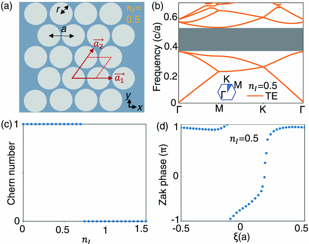
The proposed non-Hermitian PC structure is based on a two-dimensional PC comprising triangular lattices of air holes of radius embedded in a dielectric slab of , as shown in Fig. 1(a). is the lattice constant, and () represents the loss of materials, which shows the non-Hermitian properties of the systems. The calculated dispersion relations of TE modes are shown in Fig. 1(b). It can be seen that there is a large photonic bandgap of normalized frequency [in normalized units of (), is the speed of light in vacuum] from 0.3830 to 0.5335.
Figure 1.(a) Schematic diagram of the proposed non-Hermitian 2D PC geometry with a triangular lattice of air holes embedded in a dielectric substrate. (b) Dispersion bands of 2D PC with a complete photonic bandgap (gray stripe) at and (), where the inset shows the unit cell with high symmetry points. (c) Chern number distribution as a function of , which shows phase transition from topology to triviality with the increasement of loss. (d) Zak phase evolution for , and is the displacement parameter along the direction.
The coordinate space is described by vectors , as depicted in Fig. 1(a). Lattice vectors are marked in Fig. 1(a). The 2D parametric space of the eigenstates can be built by Bloch wave vectors . In PCs, the inner product of the intrinsic mode is defined by the expression [23] where , are six-dimensional vectors , is the tensor of permittivity and permeability, and . The eigen state is a function of the electromagnetic field. If the medium does not have electromagnetic coupling, only the integration of the electric field or magnetic field is needed. The Berry connection of a single unit cell in the electromagnetic wave can be written as ⏧⏧⏧⏧where and are the electric and magnetic fields for the th photonic band with wave vector , respectively. It should be noted that the integral value calculated only for the magnetic field or electric field or both is different, but it does not affect the final results of the Chern numbers [30], so it is available using either the magnetic field or electric field.
The finite element method (FEM) is used to calculate the electromagnetic field. The Brillouin zone (BZ) is discretized, and the grid is small enough. Thus, the integral and derivative are replaced by the summation and difference, which are easy for numerical calculations. The Berry curvature is calculated on each cell, and finally, the sum of all cells is calculated. For a fixed , the Zak phase can be calculated in the following way:
In these equations, the eigenstates are described by the electric field. In the non-Hermitian case, the left eigenvector is no longer the conjugate transpose of the right eigenvector , and is calculated by and , respectively. Although the phases for left and right eigenvectors are different in non-Hermitian systems, the Wilson loop still keeps the gauge invariant [31]. The same eigenvectors should be chosen for states at the same locations. For example, if we discretize the BZ into four plaquettes, by using , , , or , the phase factors of the states in BZ cancel by multiplying twice, so each eigenstate has an arbitrary phase factor, but it does not affect the calculated results. In the calculation of Zak phase, we can use only the right eigenvector due to the form of .
In Fig. 2(a), our proposed twisted piecing PC is formed by joining the normal lattice and twisted lattice. We define as a displacement parameter in the direction. For the twisted lattice, it satisfies the relationship . For a fixed , the calculated Chern number that evolves with is shown in Fig. 1(c). As the loss increases to a critical value, the Chern number changes from one to zero, meaning that the phase varies from topology to triviality. In the case of , as depicted in Fig. 1(d), when changes by a lattice constant, the Zak phase for each band will change by and the Chern number is one, which proves its topological properties.
Figure 2.Topological rainbow effect at the interface of two kinds of PCs with different topological properties in non-Hermitian system. (a) Schematic diagram of the proposed 2D topological PC. The solid black line illustrates the interface between trivial PC (normal lattice) and topological PC (twisted lattice). (b) Map of the group velocity distribution as a function of and frequency. All dashed lines denote zero group velocity. (c) Normalized electric field distributions of along the direction.
The topological photonic interface can be formed by the splicing trivial PC (undeformed lattice) and topological PC (twisted lattice), as depicted in Fig. 2(a). The area of the structure is . The red dot “” is the origin of the axis and represents the center of rotation. The red point “” depicts the location where the air hole center intersects with the axis along the direction of the reverse extension line of . We introduce parameter to represent the distance between and , and is the twisted angle. The solid black line illustrates the interface between topological and trivial PCs. Interface states will be constructed at the interface, and an interesting topological rainbow phenomenon can be found, so the twisted piecing PC provides a new degree of freedom to modulate the topological photonic states propagating along this interface. Figure 2(c) shows eigenmode field distributions of TE mode at . It is clear that different frequencies of topological photonic states are trapped into different positions along the interfaces of structures to form the topological rainbow trapping.
Group velocity can be further used to demonstrate the physical mechanism of topological rainbow forming from the perspective of the slow light effect. The group velocity of the interface state can be calculated by numerical integration according to the equation ⏧⏧⏧
The electric field and magnetic field are calculated by the FEM eigen solver provided by the software COMSOL Multiphysics, and is the unit vector along the interface [21]. Figure 2(b) shows the distribution of group velocity of the interface states as a function of frequencies and translation parameter . The color depth represents the magnitude of group velocity of the interface states. The dark regions are without interface states, and the bright region is where the interface states exist. The green dashed lines mark the boundaries of the three regions, and are the zero group velocity lines where the states will stop. In such a topological structure, the incident plane wave at a certain frequency will be slowed down from propagating forward due to the decreasing-to-zero group velocity at this spatial position, and the wave eventually approaches “stopping” in principle between the domain walls, forming topologically protected states. As depicted in Fig. 2(c), it is clear that electric fields are highly concentrated at the interface (slow light state with low group velocity) and transport forward with the varying of the frequency. Therefore, the interface states of different frequencies will be located at different positions, and topological rainbow trapping can occur.
B. Topological Rainbow Tuned by Loss
Topological rainbow trapping can also be tuned by loss in the non-Hermitian system. Evidently, the operating frequency range of a rainbow depends on the frequency range of interface states. The loss can influence the movement of bands by engineering band dispersion, so the operating frequency of the topological rainbow trapping in non-Hermitian systems can be tuned by loss. Take a state with normalized frequency for example; the interface state distributions with different losses are shown in Fig. 3(a). The coordinate represents the distance from the origin to the position of topological states along the splicing interface, and the axis shows the electric field intensity. Different colors indicate different imaginary parts of the refractive index of the medium, that is, different losses are applied. It is clear that the interface states are located at different positions with the variation of loss. Predictably, the interface states of any frequencies located at the splicing of the structure all satisfy this law. In a nutshell, the interface state frequencies of rainbow devices can be tuned by the loss of medium materials. The electric field distribution with different losses is depicted in Fig. 3(b). The interface states with the frequency of are trapped in different locations tuned by different losses.
Figure 3.(a) Position and electric intensity distribution for the photonic state of frequency , which is controlled by loss. Loss can tune the operating frequency of interface states. (b) Normalized electric field distributions of of the certain state in (a) under different losses.
The method of constructing the topological rainbow trapping effect based on our proposed lossy PCs can also be used for the TM mode. The calculated dispersion relations of TM and TE modes are shown in Fig. 4(a), where the inset shows the supercell for calculations with high symmetry points, and blue and orange solid lines represent the bulk states of TM and TE modes, respectively. It can be seen that TE possesses a large photonic bandgap and TM possesses a complete overlap with the TE bandgap. By appropriately modifying the dielectric constant or air hole radius, the complete bandgap can be enlarged. Figure 4(b) shows field distributions of TM mode at . Light with different frequencies will stop at different spatial positions along the direction of propagation, and rainbow trapping occurs. Because our topological rainbow trapping is based on the nontrivial topology induced by twisted deformation, the conclusion can be easily generalized to other lattice types and structures in TE or TM mode, as long as the complete bandgap exists.
Figure 4.(a) Dispersion bands of 2D non-Hermitian PC of triangular lattice with a complete photonic bandgap (gray stripe). Blue and orange solid lines represent TM and TE mode bulk states, respectively. (b) Normalized electric field distributions of of topological rainbow phenomenon in TM mode.
Figure 5.(a) Structure of proposed non-Hermitian 2D PC with fewer disorders. (b) Normalized electric field distributions of of topological rainbow phenomenon with fewer disorders in TE mode.
To further demonstrate the robustness of the topological rainbow device, some disorders are introduced by changing the positions and radii of the air holes around the interface of our proposed structure. First, consider the case with fewer perturbations, as shown in Fig. 5(a). The holes marked by red arrows have moved by the distance of , and they are located at the unit cells near the interface. A little bit farther away from the boundary, the circular hole has shrunk by , indicated with red arrows. At the same time, the air hole is missing as indicated by white dotted circles. The electric intensity distributions in TE mode are shown in Fig. 5(b). The frequencies of interface states are affected due to the disorders, compared with Fig. 2(c), but the photonic states can still be separated and trapped at different locations along the interface. This further verifies the robustness of the designed rainbow device.
Furthermore, we continuously increase perturbations to probe the robust limitations of the structure. As shown in Fig. 6(a), we keep the translations of holes at the same positions, and make the contraction and missing of the holes occur closer to the boundary. The parameters and remain unchanged. Clearly, this will have a larger effect on the distribution of interface states. It can be seen from Fig. 6(b) that under the effects of strong disorders, the locality of interface states is damaged, such as and , and a part of light flows into the structure, which reduces the electric intensity distribution of interface states by about . In addition, the frequencies of these states have also been changed by about . However, the interface states at the ends of the structure along the direction are almost unchanged because they are less affected by perturbations.
Figure 6.(a) Structure of proposed non-Hermitian 2D PC with bigger disorders. (b) Normalized electric field distributions of of topological rainbow effect with bigger disorders in TE mode, which are affected by disturbances.
In addition, we consider the overall variation of the radius of circular holes due to the interferences of external conditions. From Figs. 7(a)–7(c), the bulk bands of unit cells with radii of , , and are calculated, respectively. With the increase of radius, the bands gradually move up and the gaps gradually get narrow. When the radius is small, the wide bandgap provides more operational spaces for the design and machining of topological rainbow devices. As the radius gets larger, the bandgap becomes narrower, which is not conducive to frequency division, and when a limit value is reached, the rainbow effect disappears. Figures 7(d) and 7(e) show field distributions in the cases of and , respectively. Compared with the distributions of states shown in Fig. 2(c) (), it can be seen clearly that the rainbow effect has lower frequencies and larger work regions when the radius is . When the radius is , the frequencies become higher and the intervals become narrower. In addition, the localization of the light becomes weaker, leading to some discretization and a significant decrease in the electric field strength. If the radius becomes larger, the implementation of rainbow devices will be threatened.
Figure 7.(a) Calculated energy bands of unit cells for different radii, which show apparent changes of bandgaps. (b) Normalized electric field distributions of of topological rainbow phenomena in cases of and . The performances of rainbow devices are affected by the increase of radius.
To show the influence of rotated angles on the performance of topological rainbow devices, we have calculated the electric intensity distributions of different interface states when the rotated angle is 12°. Different rotated angles correspond to different shifted distances of for air holes in the direction, and so correspond to different frequencies of interface states as depicted in Fig. 2(b). However, the bandgap will not be influenced, which means the rainbow effect will not be affected. Figure 8(a) is the geometry structure, and the calculated intensity distributions of the rainbow are shown in Fig. 8(b). Compared with the original rainbow distributions with a rotated angle of 13°, the frequencies of interface states shift, but the spatially dispersed interface states still exist under the change of rotated angles.
Figure 8.(a) Schematic diagram of the proposed 2D topological rainbow structure with different angles. (b) Normalized electric field distributions of along the direction when the rotated angle is 12°.
In summary, the robustness of our proposed topological structures is not absolute. But when the perturbations added to the device are not serious, our structure has great robustness. The pure dielectric material silicon is easy to process, so it has excellent application prospects in the design of low loss and anti-interference nanophotonic devices.
5. CONCLUSION
In conclusion, topological rainbow trapping based on twisted piecing all-dielectric PCs in non-Hermitian systems has been realized for the first time, where topological states with different frequencies can be separated and trapped in different locations. This work simulates real device conditions by studying non-Hermitian PCs with loss, since the real world is composed of open non-Hermitian systems. Loss is generally unfavorable for photonic devices, but in this work, loss is taken as a new degree of freedom to control the operating frequency, which is an effective approach in non-Hermitian systems. Moreover, the rainbow trapping effect can be achieved in both TE and TM modes. The topological principle discussed here is free of symmetry restrictions, as long as a complete bandgap exists, so it can be easily generalized to other lattice types. This work provides a method to design topological photonic devices with the advantages of robustness in real systems, such as wavelength routers, multichannel optical amplifiers, optical storages, and optical buffers.
Acknowledgment
Acknowledgment. Cuicui Lu acknowledges the helpful discussions with Prof. Yong-Chun Liu in Tsinghua University.