
Pingyang Shi, Guiling Wu, Liang Hu, Qi Li, Jianping Chen. Stable RF transfer over a fiber-optic ring with DSBCS modulation and a DSB RF signal[J]. Chinese Optics Letters, 2020, 18(2): 020603
- Chinese Optics Letters
- Vol. 18, Issue 2, 020603 (2020)
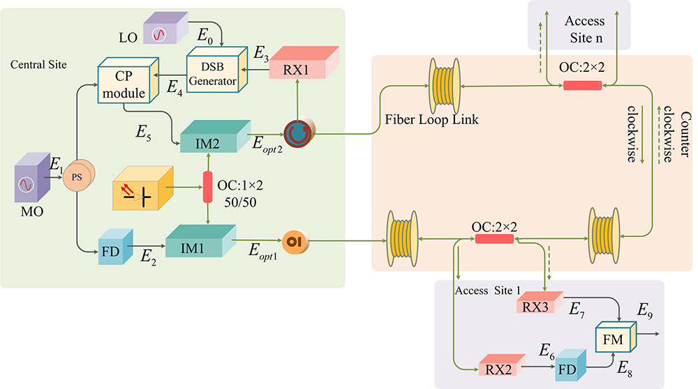
Fig. 1. Schematic diagram of the proposed fiber-optic frequency transfer scheme. MO, master oscillator; LO, local oscillator; IM, intensity modulator; RX, receiver; DSB generator, double-sideband generator; CP module, conjugated phase module; OC, optical coupler; OI, optical isolator; FD, frequency divider; FM, frequency mixer.
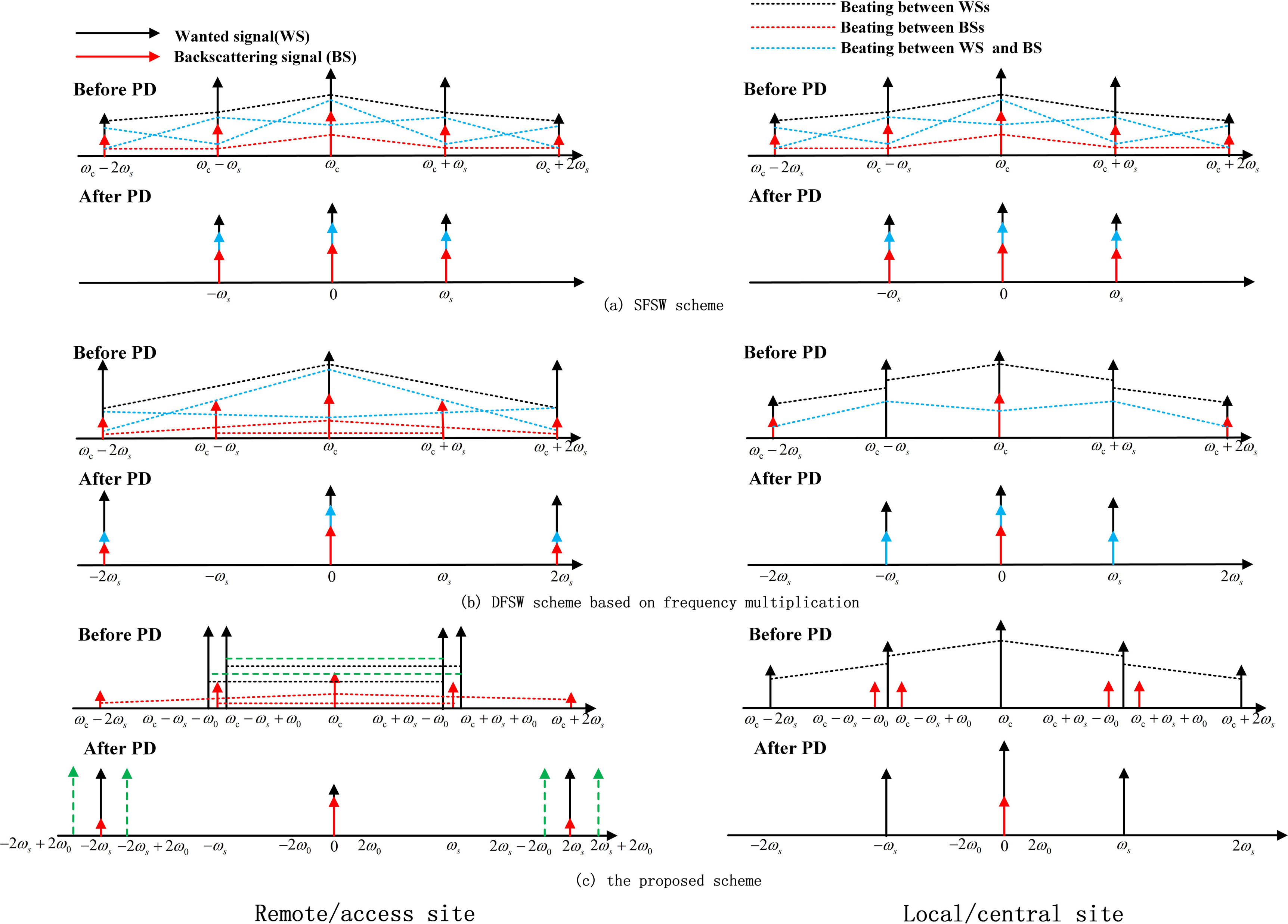
Fig. 2. Diagram of signals before and after the PD at the remote/access site (left) and the local/CS (right) in (a) the SFSW scheme, (b) DFSW scheme based on frequency multiplication, and (c) the proposed scheme. WS, wanted signal; BS, backscattering signal.
Fig. 3. Experimental setup of the proposed passive fiber-optic RF transfer. EC, electrical coupler; EDFA, erbium-doped fiber amplifier; Bi-EDFA, bidirectional erbium-doped fiber amplifier; PSB, polarization scrambler board; BPF, band-pass filter; PD, photodetector; DFM, dual frequency mixer.
Fig. 4. (a) Measured phase noise spectra at 10 MHz and (b) Allan deviations of different fiber-optic frequency transfer systems.

Set citation alerts for the article
Please enter your email address
© Copyright 2018-2021 | Chinese Laser Press. All Rights Reserved 沪ICP备15018463号-20