1Shanghai Institute for Advanced Communication and Data Science, State Key Laboratory of Advanced Optical Communication Systems and Networks, Department of Electronic Engineering, Shanghai Jiao Tong University, Shanghai 200240, China
2Shanghai Key Laboratory of Navigation and Location-Based Services, Shanghai 200240, China
Pingyang Shi, Guiling Wu, Liang Hu, Qi Li, Jianping Chen, "Stable RF transfer over a fiber-optic ring with DSBCS modulation and a DSB RF signal," Chin. Opt. Lett. 18, 020603 (2020)
Copy Citation Text
We propose a radio frequency (RF) transfer technique with passive phase noise compensation over a fiber-optic ring. By adopting different frequencies and same wavelength transmission and double sideband (DSB) with carrier suppression (DSBCS) modulation, the impact of backscattering can be effectively suppressed. A stable RF signal can be obtained via frequency mixing at an arbitrary access site along the fiber-optic ring. As the two directional transmissions adopt the same fiber and same wavelength from the same laser, the bidirectional propagation symmetry can be maximally guaranteed. We experimentally demonstrate 2 GHz RF signal transfer along a 100 km standard single-mode fiber-optic ring.
Many advanced applications require high-precision frequency dissemination, such as radio astronomy, particle accelerators, and remote clock comparison[1,2]. Fiber-optic radio frequency (RF) dissemination has attracted more and more attention over the last decades because of its unique advantages of broad bandwidth, low loss, high immunity to environmental perturbation, etc. Active[3–7] and passive[8–13] phase noise compensation schemes have been widely adopted to suppress the phase noise introduced by the temperature fluctuations and mechanical vibrations on the fiber links. In comparison with active compensation schemes, passive phase noise compensation schemes can realize faster compensation and unlimited dynamic range by using a relatively simple frequency mixing technique. In order to support multi-user applications, such as square kilometer array (SKA)[14], point-to-multipoint RF transmission has been demanded by using bus, star, and ring fiber-optic topology structures[9,10,15]. Among these structures, ring topology has better compatibility with existing optical networks[14,16,17]. RF dissemination over a fiber ring with the same frequency and the same wavelength (SFSW) transmission and bidirectional wavelength-division multiplexing (WDM) transmission has been proposed and experimentally demonstrated[6,9,16,18]. However, the SFSW-based RF transfer scheme is limited by Rayleigh backscattering and stray optical reflections on connectors[19,20], whereas the bidirectional WDM-based RF transfer scheme suffers from bidirectional asymmetry due to the different wavelengths, resulting in the degradation of the phase noise compensation performance[5,21]. In Ref. [22], Wei et al. proposed a passive phase noise compensation approach for highly stable RF phase transfer via an optical fiber by frequency mixing. By adopting the bidirectional different frequencies and same wavelength (DFSW) transmission technique, the bidirectional propagation symmetry can be guaranteed, and the effect of self-beating of the backscattering signal (BS) can be effectively suppressed at the same time. However, this scheme cannot suppress the effect of the beating between the transferred signal and the BS, which is much larger than the self-beating of the BS[23]. In Ref. [5], Zhang et al. proposed an active phase noise compensation scheme with a carrier suppressed double-sideband (DSB) RF signal, where the effect of the mutual beating between the transferred signal and the BS can be effectively suppressed.
In this Letter, we propose a passive phase noise compensation scheme for a fiber-optic ring network. In the scheme, a DSB RF signal, modulated onto an optical carrier by using DSB with carrier suppression (DSBCS) modulation, is adopted to achieve bidirectional DFSW transmission. By combining the DSB RF signal-based DFSW transmission and DSBCS modulation, the impact of the backscattering can be effectively suppressed. At the same time, the propagation symmetry can also be guaranteed by using the same wavelength from the same laser along the same fiber for both directions. A stable RF signal can be obtained at any access site over the 100 km optical fiber ring. The results show that a relative frequency stability of less than 2.95 × 10⁻¹⁴/s and 4.05 × 10⁻¹⁷/10,000 s can be achieved at any access site.
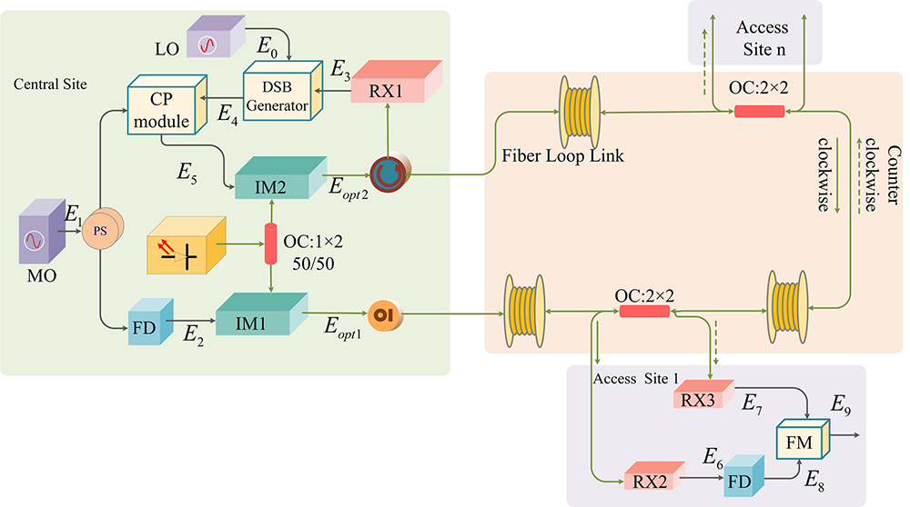
The proposed scheme is illustrated in Fig. 1. At the central site (CS), the transferred signal from the master oscillator (MO) can be denoted as where and are the angular frequency and initial phase of the signal from the MO, respectively. The transferred RF signal is split into two branches by a power splitter (PS). By dividing the frequency of one branch signal by a factor of 2, we can have
Sign up for Chinese Optics Letters TOC. Get the latest issue of Chinese Optics Letters delivered right to you!Sign up now
Figure 1.Schematic diagram of the proposed fiber-optic frequency transfer scheme. MO, master oscillator; LO, local oscillator; IM, intensity modulator; RX, receiver; DSB generator, double-sideband generator; CP module, conjugated phase module; OC, optical coupler; OI, optical isolator; FD, frequency divider; FM, frequency mixer.
Then, the frequency divided signal is modulated onto an optical carrier by using an intensity modulator 1 (IM1) biased at . The output optical field of IM1 can be written as where is the optical frequency of the optical carrier, , , and are the constant coefficients related to the modulation parameters, and represents the higher components.
The modulated optical signal is transmitted over the fiber ring along the counterclockwise direction and back to the CS, in which it is detected by receiver 1 (RX1), and the output can be expressed as where is the propagation delay along the entire fiber ring. The recovered signal is mixed with an auxiliary signal of [ and are the angular frequency and initial phase of the signals from the local oscillator (LO)] by using a DSB generator to produce a DSB RF signal of ;
By mixing with in the phase-conjugated (PC) module, we can produce a PC RF DSB signal with an expression of
Afterwards, the PC is modulated on the same optical carrier from the same laser by using IM2 biased at to produce a DSBCS optical signal; where is a constant coefficient related to the modulation parameters, and represents the higher components. The DSBCS optical signal is transmitted over the fiber ring along the clockwise direction.
This way, the counter-propagation optical signals from two directions are extracted from the fiber link by using a optical coupler at an arbitrary access site along the fiber loop. The extracted clockwise DSBCS signal and counterclockwise probe signal are detected by RX2 and RX3 to produce signals of and , respectively: where and are the fiber link propagation delays introduced by the clockwise and counterclockwise transmission paths between the CS and the arbitrary access site. By dividing the frequency of by a factor of 2, we can have
By mixing with , the upper sideband is filtered out, and the result can have an expression of
Since the transmissions in both directions are over the same fiber link with the same wavelength, both bidirectional propagation signals will have the same propagation delay. We have
In this way, the RF signal for can be depicted as
We can clearly see that a reproduced RF signal at an arbitrary access site can be achieved with the proposed passive phase noise cancellation. The MO is stable enough, so the phase of the MO can be described as time-invariant during a round-trip time[8].
Figure 2 illustrates the signals before and after the photodetector (PD) at the access/remote site and the local/CS for the SFSW scheme, the DFSW scheme based on frequency multiplication in Ref. [22], and the scheme proposed here, respectively. The effect of the backscattering can be evaluated by analyzing the beating among these signals that are received by the PD. At the access/remote site, the wanted signal (WS) is the delivered signal and the BS mainly comes from the probe signal. In the SFSW scheme, the wanted RF signal is produced by the self-beating of adjacent sidebands in the WS (black dot lines). Both the self-beating of adjacent sidebands in the BS (red dot lines) and the beating between the WS and the BS (blue dot lines) will generate undesirable signals with the same frequency as the wanted RF signal. In the DFSW scheme, this problem can be partially solved, where the main noise components are produced by the beating between the carrier in the BS (WS) and the second-order sidebands in the WS (BS), and the self-beating between the carrier and the second-order sidebands and two first-order sidebands in the BS.
Figure 2.Diagram of signals before and after the PD at the remote/access site (left) and the local/CS (right) in (a) the SFSW scheme, (b) DFSW scheme based on frequency multiplication, and (c) the proposed scheme. WS, wanted signal; BS, backscattering signal.
In the proposed scheme, only the self-beating between the carrier and the second-order sidebands and two first-order sidebands in the BS will generate undesirable signals with the same frequency as the wanted RF signal, which has much less effect on the RF dissemination[23]. At the local/CS (see the right of Fig. 2), the WS is the probe signal, and the BS is mainly from the delivered signal. In the SFSW scheme, the effect of BS at the local site is the same as that at the remote site. In the DFSW scheme based on frequency multiplication, the effect of the self-beating of BS can be avoided. In the proposed scheme, the effect of all noise terms related to BS will be effectively suppressed.
It is worth noting that the effect of the self-beating of BS can be suppressed by changing the way to produce in the proposed scheme. As shown by green lines, the two signals of and (green arrows) at the access site can be mixed to produce a signal of , which is then divided by a factor of 4 to obtain the signal of . Since the two signals of and can be distinguished from any other self-beating noise, the effect of the self-beating of BS can be suppressed by filtering. The system, however, will become more complex.
The experimental setup is shown in Fig. 3. At the CS, a 2 GHz standard RF signal generated from the MO is split into two branches, and the frequency of the RF signal on one branch is divided by two to generate a 1 GHz probe signal. The probe signal is modulated on an optical carrier with a wavelength of 1550.120 nm by an IM biased at . The laser used in our experiment has a linewidth of about 100 kHz. The modulated optical signal is transmitted along with the fiber loop link and back to the CS. The received probe signal is mixed with a 100 MHz local RF signal to generate 0.9 and 1.1 GHz RF signals in the DSB generator. These two signals are then, respectively, mixed with the 2 GHz standard RF signal to generate PC 0.9 and 1.1 GHz RF signals in the PC module. The PC signals are modulated onto the same light by another IM biased at . At an arbitrary access site along the fiber loop, the counterclockwise and clockwise transmission optical signals are extracted from the fiber link by using a (50/50) optical coupler. A 1 GHz signal is obtained from the counterclockwise probe signal by using a 2 GHz PD and a band-pass filter (BPF) with the 1 GHz central frequency and 3 dB bandwidth of 70 MHz. Another 1 GHz signal can also be achieved from the clockwise DSBCS signal by using a 2 GHz PD, 2 GHz BPF, and a frequency divider. The two 1 GHz signals are injected into a dual frequency mixer (DFM) to obtain a reproduced 2 GHz RF signal. The DFM is used to avoid harmonic interference[8,10]. The fiber loop link is composed of four standard single-mode fiber (SMF) spools of 20 km, 20 km, 10 km, and 50 km, placed in the lab room with temperature fluctuations about . The dispersion of each fiber spool is compensated by the corresponding dispersion compensated fiber (DCF). In order to reduce the effect of polarization mode dispersion (PMD), a polarization scrambler is implemented after the laser. To boost the fading bidirectional optical signals, a bidirectional erbium-doped fiber amplifier (Bi-EDFA) is employed between the 20 km and 10 km fiber spools. The structure of the Bi-EDFA is similar to the one previously used in Ref. [4], which can effectively suppress the backscattering noise and amplified spontaneous emission (ASE) noise. In order to evaluate the performance of the proposed scheme, the reproduced and the standard RF 2 GHz signals are converted to 10 MHz by a dual mixer method[24]. Both signals are connected with the phase noise measurement (Symmetricom Inc., TSC5120A).
The measured phase noise spectra at the access sites of 50 km (50/50) and 80 km (80/20) from the CS along the clockwise direction are shown in Fig. 4(a). The 100 km free running link is evaluated by transmitting a 1 GHz signal along the counterclockwise direction and recovering it at the access site. A 1 GHz fiber-optic frequency transfer link with SFSW transmission presented in Ref. [6] is also measured. At the offset frequency of less than 0.01 Hz, the phase noise of the 100 km free running link (−23 dBc/Hz at 10−4 Hz and −65 dBc/Hz at 1 × 10⁻³ Hz) is higher than the 1 m proposed compensated link (−70 dBc/Hz at 10−4 Hz and −88 dBc/Hz at 10−3 Hz), which is measured by connecting the CS with two 0.5 m fibers while the access site is in the middle, due to the fiber delay fluctuations caused by the temperature perturbations of the fiber link. In contrast, the phase noise of all the 100 km compensated link cases at the offset frequency of less than 0.01 Hz is close to the floor noise, indicating that the low-frequency part of the noise induced by the fiber link has been effectively compensated. When the offset frequency is larger than 1 Hz, the phase noise of the fiber link is mostly related to the RF circuits, fiber backscattering, and erbium-doped fiber amplifiers (EDFAs). We can see that the 100 km SFSW compensated link is the worst because of having all those effects in this case. Both the 100 km proposed compensated link cases outperform the SFSW transmission link since the effect of backscattering is effectively suppressed. The 100 km free running link is the best in the 1–100 Hz offset frequency range, since there is no noise effect coming from backscattering and RF circuits. After about 100 Hz of the offset frequency, the phase noise is mainly affected by the signal-to-noise ratio (SNR)[25], so the 1 m proposed compensated link has the best performance. In comparison with the case of the 50/50 access site, the 80/20 access site is limited by a lower SNR of the received clockwise signal along the 80 km fiber link with higher attenuation, and the phase noise at large offset frequency can be improved by using a high-quality quartz oscillator[8].
Figure 4.(a) Measured phase noise spectra at 10 MHz and (b) Allan deviations of different fiber-optic frequency transfer systems.
Figure 4(b) shows measured Allan deviations of different transfer links with a 5 Hz measurement bandwidth. As we can see, Allan deviations of all the compensated links scale down with the trend of . In comparison with the 100 km free running link, the short-term stability of the 100 km proposed compensated link is improved from about 7.02 × 10⁻¹⁴/s to 2.95 × 10⁻¹⁴/s. This value is close to the 1 m link with a stability of about 8.42 × 10⁻¹⁵/s. The short-term stability of the 100 km SFSW compensated link can only reach about 8.54 × 10⁻¹⁴/s, which is even worse than that of the 100 km free running link, because of the effect of the backscattering noise, whereas the long-term stability of the 100 km proposed compensated link can reach 4.05 × 10⁻¹⁷/104 s, which is improved about three orders of magnitude compared to the uncompensated link case. Moreover, the Allan deviation of the 100 km compensated link cases is larger than that of the 1 m proposed compensated link, which is mainly coming from the noise of the source signals, electronic components, and EDFA’s noise[17,26].
Nevertheless, the Allan deviation of the 80/20 and 50/50 access site is almost the same, which shows that our proposed scheme can reproduce the delivered RF signals at any site. In comparison with the 40 km compensated scheme in Ref. [5], better long-term stability can be achieved at longer distances by using our proposed compensated scheme. This is mainly because the proposed scheme can reach a higher symmetry of the bidirectional propagation by using only a single laser for two directional transmissions.
It is worth noting that the number of access sites can be increased by adding Bi-EDFAs in the fiber loop to compensate for the power loss. Although added Bi-EDFAs may increase backscattering noise, its effect can be neglected since the proposed scheme can effectively suppress the effect of backscattering.
In summary, we proposed and experimentally demonstrated a multi-access RF transfer scheme with passive phase noise compensation over a fiber-optic ring. The effect of backscattering can be effectively suppressed by using the DFSW transmission and DSBCS modulation. The symmetry of the bidirectional propagation can be guaranteed by using only a single laser in the CS. A 2 GHz signal transfer based on the proposed scheme over a 100 km fiber loop link is experimentally demonstrated. The reproduced RF signal at the access site has relative frequency stabilities of less than 2.95 × 10⁻¹⁴/s and 4.05 × 10⁻¹⁷/10,000 s.
References
[1] J. Frisch, D. Bernstein, D. Brown, E. Cisneros. Proceedings of the Particle Accelerator Conference, 816(2002).
[2] J. F. Cliche, B. Shillue. IEEE Control Systems, 26, 19(2006).
Pingyang Shi, Guiling Wu, Liang Hu, Qi Li, Jianping Chen, "Stable RF transfer over a fiber-optic ring with DSBCS modulation and a DSB RF signal," Chin. Opt. Lett. 18, 020603 (2020)