
Ji Yunbing, Liang Jingqiu, Liang Zhongzhu, Lü Jinguang, Qin Yuxin, Wang Weibiao, Tao Jin, Meng Dejia. Optical Design of Infrared Bispectrum Fourier Transform Imaging Spectrometer[J]. Acta Optica Sinica, 2018, 38(3): 322001
- Acta Optica Sinica
- Vol. 38, Issue 3, 322001 (2018)
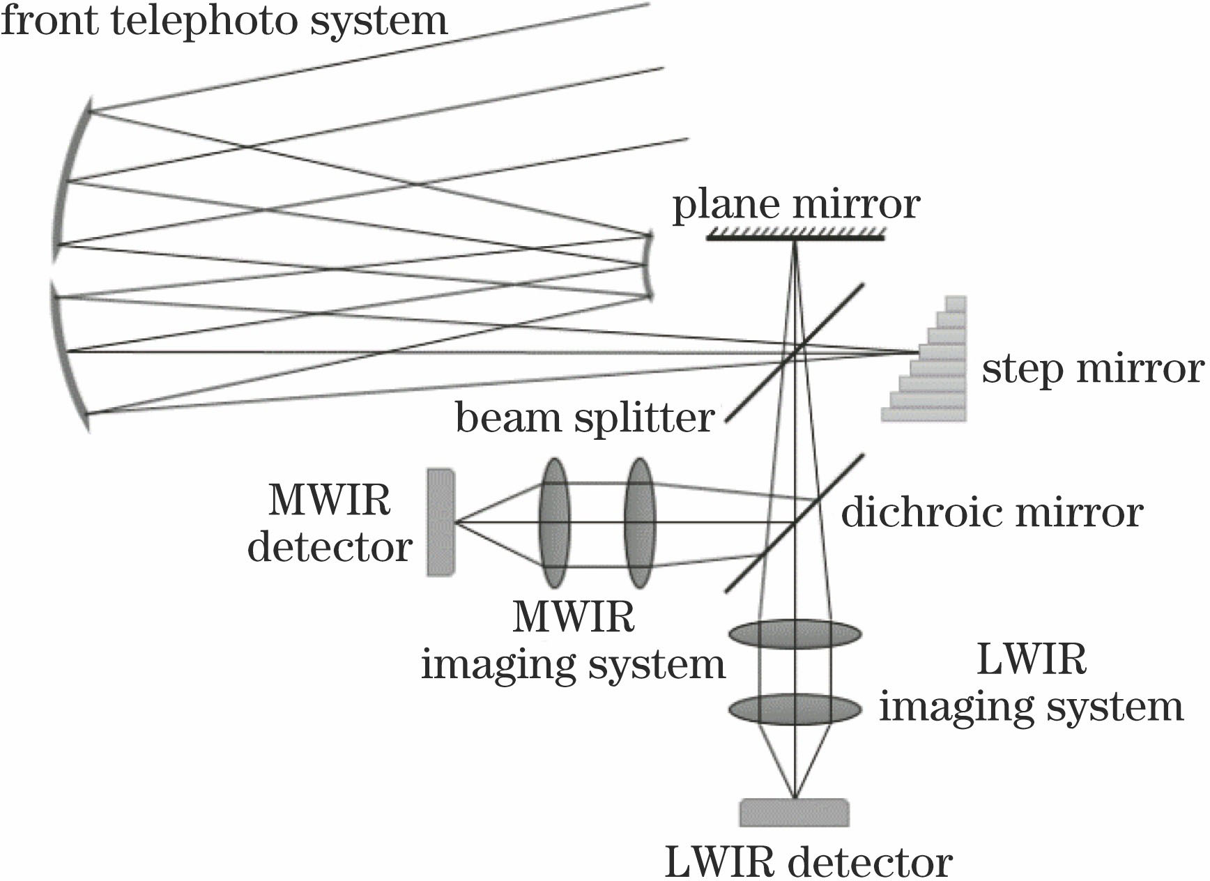
Fig. 1. Working principle of imaging spectrometer
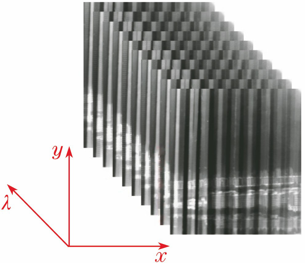
Fig. 2. Tridimensional data cube
Fig. 3. Schematic diagram of coaxial three mirror system
Fig. 4. Schematic diagram of rectangular field of view
Fig. 5. Optimized structure diagram of the front telephoto system
Fig. 6. (a) Medium wave MTF; (b) long wave MTF
Fig. 7. (a) Structure diagram; (b) MTF curve; (c) spot diagram of medium wave post-imaging system
Fig. 8. (a) Structure diagram; (b) MTF curve; (c) spot diagram of long wave post-imaging system
Fig. 9. (a) Structure diagram; (b) MTF curve; (c) spot diagram of medium wave channel overall system
Fig. 10. (a) Structure diagram; (b) MTF curve; (c) spot diagram of long wave channel overall system
|
Table 1. Main specifications of the imaging spectrometer
|
Table 2. Parameters of the front telephoto system
|
Table 3. Initial structural parameters of the front telephoto system
|
Table 4. Optimized structural parameters of the front telephoto system
|
Table 5. Parameters of medium wave post-imaging system
|
Table 6. Parameters of long wave post-imaging system

Set citation alerts for the article
Please enter your email address
© Copyright 2018-2021 | Chinese Laser Press. All Rights Reserved 沪ICP备15018463号-20