• Journal of Infrared and Millimeter Waves
  • Vol. 40, Issue 2, 248 (2021)
Xuan LI1、2, Fei LIU1、2、3、*, and Xiao-Peng SHAO1、2、3
Author Affiliations
  • 1School of Physics and Optoelectronic Engineering,Xidian University,Xi’an 710071,China
  • 2Xi’an Key Laboratory of Computational Imaging,Xi’an 710071,China
  • 3Academy of Advanced Interdisciplinary Research,Xi’an 710071,China
  • show less
    DOI: 10.11972/j.issn.1001-9014.2021.02.016 Cite this Article
    Xuan LI, Fei LIU, Xiao-Peng SHAO. Research progress on polarization 3D imaging technology[J]. Journal of Infrared and Millimeter Waves, 2021, 40(2): 248 Copy Citation Text show less
    Polarization 3D imaging of different materials
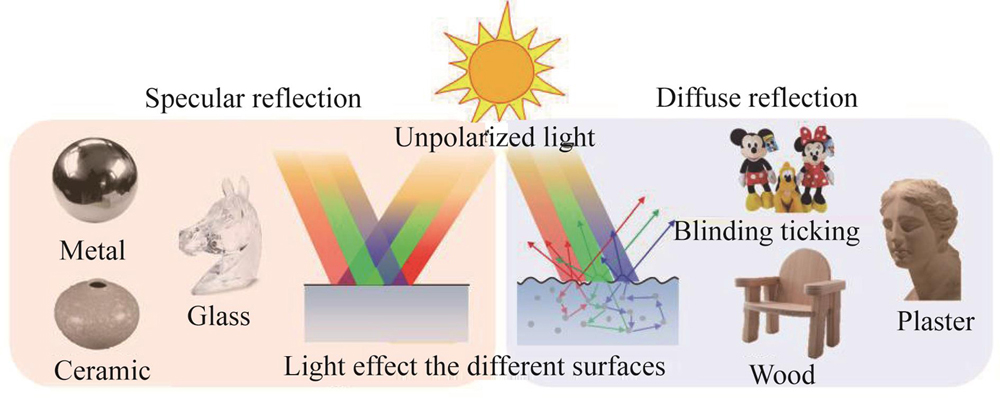
    Fig. 1. Polarization 3D imaging of different materials
    Schematic of normal vector[18]
    Fig. 2. Schematic of normal vector[18]
    Measurement process of polarization 3D imaging[19]
    Fig. 3. Measurement process of polarization 3D imaging[19]
    The s and p components of reflected and refracted light[19]
    Fig. 4. The s and p components of reflected and refracted light[19]
    Reflected light from surfaces of different types[24]
    Fig. 5. Reflected light from surfaces of different types[24]
    The relationship between the polarization degree information and the incident angle of the reflected light with different refractive indices (a) based on specular reflection light[18], (b) based on specular diffuse light[25]
    Fig. 6. The relationship between the polarization degree information and the incident angle of the reflected light with different refractive indices (a) based on specular reflection light[18], (b) based on specular diffuse light[25]
    Transmitted radiance sinusoid. The variation of light intensity information with the rotation angle of polarizer[27]
    Fig. 7. Transmitted radiance sinusoid. The variation of light intensity information with the rotation angle of polarizer[27]
    The target information acquisition process involves rotating the target at a small angle[28]
    Fig. 8. The target information acquisition process involves rotating the target at a small angle[28]
    Solution to the ambiguity of incident angle[28] (a) degree of polarization, (b) areas divided by Brewster's corner, (c) the relation curve between degree of polarization and incident angle, (d) derivative of degree of polarization
    Fig. 9. Solution to the ambiguity of incident angle[28] (a) degree of polarization, (b) areas divided by Brewster's corner, (c) the relation curve between degree of polarization and incident angle, (d) derivative of degree of polarization
    Results of 3D imaging[29] (a) transparent hemisphere, (b) transparent frustum of a cone, (c) transparent semi-lens, (d) - (f) 3D imaging results corresponding to the target on its left
    Fig. 10. Results of 3D imaging[29] (a) transparent hemisphere, (b) transparent frustum of a cone, (c) transparent semi-lens, (d) - (f) 3D imaging results corresponding to the target on its left
    Relationship between incident angle and degree of polarization[35] (a) infrared light, (b) visible light
    Fig. 11. Relationship between incident angle and degree of polarization[35] (a) infrared light, (b) visible light
    Results of 3D imaging[37] (a) diffuse intensity of the target, (b) estimated shape, (c) estimated shape is viewed from lateral view
    Fig. 12. Results of 3D imaging[37] (a) diffuse intensity of the target, (b) estimated shape, (c) estimated shape is viewed from lateral view
    Grayscale images of smooth porcelain[19] (a) vase, (b) urn, (c) bear, (d) slightly rough plastic duck, (e) – (h) phase images showing angle of polarization, (i) – (l) degree of polarization, dark areas have highest polarization, (m) – (p) normal vectors (reduced resolution)
    Fig. 13. Grayscale images of smooth porcelain[19] (a) vase, (b) urn, (c) bear, (d) slightly rough plastic duck, (e) – (h) phase images showing angle of polarization, (i) – (l) degree of polarization, dark areas have highest polarization, (m) – (p) normal vectors (reduced resolution)
    Polarization curve of different incident light wavelength[40]
    Fig. 14. Polarization curve of different incident light wavelength[40]
    3D reconstruction of transparent targets with partial high slope[40] (a) intensity image, (b) degree of polarization, (c) 3D reconstruction result
    Fig. 15. 3D reconstruction of transparent targets with partial high slope[40] (a) intensity image, (b) degree of polarization, (c) 3D reconstruction result
    Surface reconstruction of the objects[42] (a) intensity images, (b) results after remove the highlight, (c) reconstruction results by stereo vision, (d) reconstruction results by multispectral polarization
    Fig. 16. Surface reconstruction of the objects[42] (a) intensity images, (b) results after remove the highlight, (c) reconstruction results by stereo vision, (d) reconstruction results by multispectral polarization
    Experimental diagram[46]
    Fig. 17. Experimental diagram[46]
    Acquisition principle of the segmented image[46]
    Fig. 18. Acquisition principle of the segmented image[46]
    Flowchart of the polarimetric multi-view stereo algorithm[24]
    Fig. 19. Flowchart of the polarimetric multi-view stereo algorithm[24]
    Comparison of depth estimation with Zhaopeng Cui[24], Polarized3D[51] and Smith[52, 24]
    Fig. 20. Comparison of depth estimation with Zhaopeng Cui[24], Polarized3D[51] and Smith[52, 24]
    3D reconstruction results of target plastic sphere with black color and high specularity[18] (a) - (b) shape computed by space carving for a real sphere, (c) - (d) shape computed by Daisuke Miyazaki method[18] for a real sphere
    Fig. 21. 3D reconstruction results of target plastic sphere with black color and high specularity[18] (a) - (b) shape computed by space carving for a real sphere, (c) - (d) shape computed by Daisuke Miyazaki method[18] for a real sphere
    3D reconstruction result[53] (a) intensity image of target, (b) depth estimation of target
    Fig. 22. 3D reconstruction result[53] (a) intensity image of target, (b) depth estimation of target
    Schematic diagram of imaging system[57] (a) geometric relationship of imaging system, (b) view of a spherical target object from the camera viewpoint
    Fig. 23. Schematic diagram of imaging system[57] (a) geometric relationship of imaging system, (b) view of a spherical target object from the camera viewpoint
    Surface reconstruction of the objects[57] (a) raw images of the test targets, (b) depth estimation of targets
    Fig. 24. Surface reconstruction of the objects[57] (a) raw images of the test targets, (b) depth estimation of targets
    Experiment results[59] (a) phase of polarization, (b) degree of diffuse polarization, (c) intensity, (d) reconstructed surface
    Fig. 25. Experiment results[59] (a) phase of polarization, (b) degree of diffuse polarization, (c) intensity, (d) reconstructed surface
    Imaging system[61]
    Fig. 26. Imaging system[61]
    Polarization 3D imaging in a range of lighting conditions[61] (a) ToF Kinect, (b) polarizaiton enhancement indoors, (c) polarizaiton enhancement under disco lighting, (d) polarizaiton enhancement outdoors on a partly sunny, (e) enhanced kinect depth using Kadambi method, (f) laser scanner depth
    Fig. 27. Polarization 3D imaging in a range of lighting conditions[61] (a) ToF Kinect, (b) polarizaiton enhancement indoors, (c) polarizaiton enhancement under disco lighting, (d) polarizaiton enhancement outdoors on a partly sunny, (e) enhanced kinect depth using Kadambi method, (f) laser scanner depth
    The different applications of polarization 3D imaging
    Fig. 28. The different applications of polarization 3D imaging
    Xuan LI, Fei LIU, Xiao-Peng SHAO. Research progress on polarization 3D imaging technology[J]. Journal of Infrared and Millimeter Waves, 2021, 40(2): 248
    Download Citation