• Chinese Optics Letters
  • Vol. 21, Issue 1, 010501 (2023)
Zhenpeng Song1, Ziyang Li1, Xiaohu Shang1, Chaoyi Li2, Lingling Ma2、*, Yanqing Lu2, and Bingxiang Li1、2、**
Author Affiliations
  • 1College of Electronic and Optical Engineering & College of Flexible Electronics (Future Technology), Nanjing University of Posts and Telecommunications, Nanjing 210023, China
  • 2National Laboratory of Solid State Microstructures, Key Laboratory of Intelligent Optical Sensing and Manipulation, College of Engineering and Applied Sciences, and Collaborative Innovation Center of Advanced Microstructures, Nanjing University, Nanjing 210023, China
  • show less
    DOI: 10.3788/COL202321.010501 Cite this Article Set citation alerts
    Zhenpeng Song, Ziyang Li, Xiaohu Shang, Chaoyi Li, Lingling Ma, Yanqing Lu, Bingxiang Li. Electrically switchable structural patterns and diffractions in a dual frequency nematic liquid crystal[J]. Chinese Optics Letters, 2023, 21(1): 010501 Copy Citation Text show less

    Abstract

    Electrically driven structural patterns in liquid crystals (LCs) have attracted considerable attention due to their electro-optical applications. Here, we disclose various appealing reconfigurable LC microstructures in a dual frequency nematic LC (DFNLC) owing to the electroconvection-induced distortion of the LC director, including one-dimensional rolls, chevron pattern, two-dimensional grids, and unstable chaos. These patterns can be switched among each other, and the lattice constants are modulated by tuning the amplitude and frequency of the applied electric field. The electrically switchable self-assembled microstructures and their beam steering capabilities thus provide a feasible way to tune the functions of DFNLC-based optical devices.

    1. Introduction

    One of the unique features of liquid crystals (LCs) is the ability to form various functional microstructural patterns in the manner of self-assembly, which enables a multitude of LC-based optoelectronic devices, including lasing[1], vortex beam generation[2,3], optical imaging[46], beam steering[79], diffractive elements[10,11], and particle manipulation[12]. Nematic LCs (NLCs) endowed with optical, dielectric, and conductive anisotropies have triggered intensive explorations on diverse electric phenomena since the first observation, to the best of our knowledge, of the Frederick transition effect almost one century ago[13]. The electric field can cause either collective reorientations or a regional modulation of the NLC directors n^, leading to non-equilibrium processes and various spatial patterns developed from a homogeneous state[1419]. Electroconvection (EC), also known as electrohydrodynamic instability, is considered as a traditional but intriguing way to generate structural patterns in NLCs, owing to the coupling of the LC elasticity, the mass/charge flow, and the induced internal electric field. The earliest and simplest example of the EC pattern was the so-called Williams domains explored in the material with negative dielectric anisotropy (Δε<0) and positive conductive anisotropy (Δσ>0), also called (,+) material for convenience[20]. This pattern was explained by the Carr–Helfrich mechanism, where the trivial thermal fluctuation of n^ permits a spatial separation of charges under the electric field, contributing to a vortex flow. In this condition, a viscous torque is generated to balance the nematic elastic torque. Thus, the distorted director distribution is stabilized, and structural nematic patterns emerge. Frequency and amplitude of the applied electric field are key parameters in the dynamic control of structural parameters, which largely facilitates tunable optic systems, while the prevailing usage of frequency ranging from 1 Hz to 1 kHz does not change the dielectric anisotropy, thus limiting the forms of created structural patterns in nematics.

    Dual frequency NLCs (DFNLCs) are special soft building blocks that possess an electric field frequency-dependent dielectric anisotropy[21,22], i.e., Δε>0 at the frequency below the crossover frequency f<fcrossover and Δε<0 for f>fcrossover. Krishnamurthy’s group reported the structural transition of EC patterns from the initial homogeneous state, umbilics, to Williams-like domains in homeotropic bent-rod DFNLCs[23], and pattern transformations from longitudinal rolls[2426], oblique rolls[24,25], lateral rolls[26], undulated rolls[24], zigzag Williams-like rolls[27], chevron texture[27], to loop domains[24,27] in planar DFNLCs. Such striped domains were also noticed by Barnik et al. and utilized in a DFNLC-based optical phase modulator[26]. Besides one-dimensional (1D) roll patterns, Kang et al. generated two-dimensional (2D) periodic structural patterns in the DFNLC MLC2048 and its mixture doped with a small amount of reactive monomer[24]. Tunable diffractive elements were also demonstrated[28,29]. Till now, there are still few investigations focusing on the systematic exploration of electrically switchable structural patterns, which provide basic limitations on the applications of DFNLCs.

    In this work, we investigate the EC enabled switchable pattern formation and the consequent beam steering in a DFNLC DP002-026 within the frequency regime where the dielectric anisotropy of the material is negative. Unexpectedly, 1D lateral and longitudinal rolls, and 2D square grids are generated and can be switched among each other by facilely altering the magnitude and frequency of the electric field. The electric dependences of pattern periodicities and diffractive parameters are investigated, which is a major step forward for the future usage of DFNLCs in structural and optical devices.

    2. Experimental Materials and Methods

    A commercially available DFNLC DP002-026 (Δn=0.263 at λ=589nm, T=25°C, Jiangsu Hecheng Display Technology) is used to investigate the electric-field-induced pattern formation and the corresponding diffraction phenomena. LC cells are assembled by using two glass plates with transparent indium tin oxide electrodes. In the experiment, we used two types of cells. One type is planar alignment cells, the inner surface of which is coated with polyimide ZKPI 4220 (Nanjing JCOPTIX); the other is homeotropic alignment cells coated with polyimide SE1211 (Germany Merck). The ZKPI 4220 coated substrates are further unidirectionally rubbed to produce an initial uniform director n^0 along the x axis. The thickness of these cells d=8.0µm is controlled by the spacers in UV glue. The DFNLC is injected into the cells in its isotropic phase. The dielectric permittivities, ε and ε, of DP002-026 are characterized using the inductance, capacitance, and resistance (LCR) meter (4284A, Hewlett-Packard) in homeotropic and planar cells, respectively. Here, we investigate the permittivities (ε and ε) of DP002-026 at different temperatures ranging from 26°C to 38°C, as shown in Fig. 1(a). The relaxation of ε starts from 10kHz and shifts toward the higher frequency region as the temperature increases. ε is almost unchanged during the change of the frequency from 10 kHz to 300 kHz. As a result, the sign inversion of dielectric anisotropy (Δε=εε) increases with the growth of temperature. For example, when the temperature changes from 26°C to 38°C, the crossover frequency fcrossover rises from 19.5 kHz to 87.2 kHz.

    (a) Frequency dependence of dielectric constants (ε∥ and ε⊥) of the DFNLC DP002-026 at various temperatures: 26°C (blue filled circle), 28°C (orange open square), 30°C (green filled rhombus), 32°C (red open triangle), 34°C (purple filled inverted triangle), 36°C (brown open circle), and 38°C (blue filled square). (b) Schematic illustration of the experimental setup for diffraction characterization. A cell is equipped in the hot stage and probed with a linearly polarized laser beam.

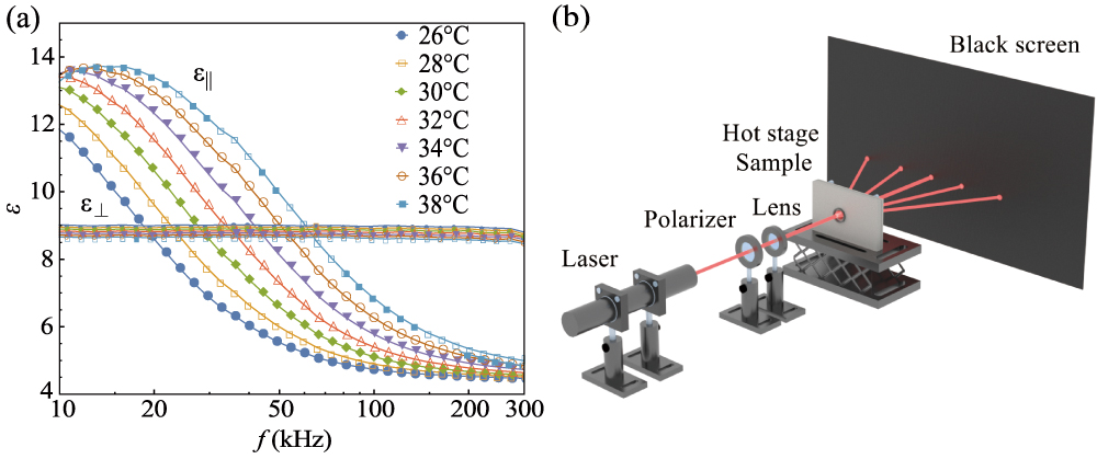
    Figure 1.(a) Frequency dependence of dielectric constants (ε and ε) of the DFNLC DP002-026 at various temperatures: 26°C (blue filled circle), 28°C (orange open square), 30°C (green filled rhombus), 32°C (red open triangle), 34°C (purple filled inverted triangle), 36°C (brown open circle), and 38°C (blue filled square). (b) Schematic illustration of the experimental setup for diffraction characterization. A cell is equipped in the hot stage and probed with a linearly polarized laser beam.

    Dielectric anisotropy of NLCs is one of the key parameters determining the existence and structure of the electrohydrodynamic pattern of the nematics. To obtain the field-induced patterns, which present the director modulation of the DFNLC, a waveform generator (RIGOL DG4162) and a voltage amplifier (Aigtek ATA-2041) are used together to provide sinusoidal alternate current (AC) voltages of amplitude ranging from 0 V to 40 V and frequency varying from 32 kHz to 47 kHz. The amplitude and frequency of the applied voltages are further measured using a digital oscilloscope (RIGOL DS1202). Consequently, the electric fields are applied perpendicular to the nematic director. The temperature in the experiments is set by using a hot stage (HCS402) and a temperature controller (mK2000B), both of which are purchased from Instec. The observation of the optical patterns is performed using a polarized optical microscope (Nikon ECLIPSE Ci-POL). To investigate the diffraction phenomena, a He–Ne laser beam of wavelength λ=632.8nm is used and passes through a linear polarizer, which tilts 45° with respect to the initial director n^0 that aligns horizontally, a lens, the LC cell, and finally generates a diffraction pattern on the black screen, as shown in Fig. 1(b).

    3. Experimental Results

    To characterize electrohydrodynamic patterns in the DFNLC DP002-026, a sinusoidal AC voltage U=16.1V is applied onto an NLC cell of thickness 8.0 µm at T=30°C, and the field frequency f is increased slowly from 28 kHz to 40 kHz. As shown in Fig. 2(a), when f=28kHz<fcrossover, the director field exhibits a uniform state; at f>fcrossover, the director field starts to be distorted. At f=30kHz, looped domains of the diameter of about 20 µm gradually appear and distribute randomly. Further increasing the frequency to f=32kHz, a disorganized chevron pattern is observed in the whole active electrode area. At f=38kHz, a square-grid pattern is present. Subsequently, a regular periodic longitude rolls pattern is observed at f=40kHz. Here, the longitudinal rolls are parallel to the initial orientation of the nematic director.

    POM images and the corresponding phase diagram of pattern formation for the DFNLC DP002-026. (a) Pattern generation as the field frequency varies from 28 kHz to 40 kHz at the voltage U = 16.1 V, the cell thickness d = 8 µm, and T = 30°C. (b) Pattern generation as the field frequency varies from 25 V to 0 V at the frequency f = 40 kHz, the cell thickness d = 8 µm, 0 V, and T = 30°C. (c) The corresponding phase diagram of pattern formation during voltage decrease for the DFNLC DP002-026 in the cell of thickness d = 8 µm and T = 30°C. The patterns are recorded using crossed polarizers and a quarter waveplate placed at 45° with respect to P. The initial nematic director aligns horizontally.

    Figure 2.POM images and the corresponding phase diagram of pattern formation for the DFNLC DP002-026. (a) Pattern generation as the field frequency varies from 28 kHz to 40 kHz at the voltage U = 16.1 V, the cell thickness d = 8 µm, and T = 30°C. (b) Pattern generation as the field frequency varies from 25 V to 0 V at the frequency f = 40 kHz, the cell thickness d = 8 µm, 0 V, and T = 30°C. (c) The corresponding phase diagram of pattern formation during voltage decrease for the DFNLC DP002-026 in the cell of thickness d = 8 µm and T = 30°C. The patterns are recorded using crossed polarizers and a quarter waveplate placed at 45° with respect to P. The initial nematic director aligns horizontally.

    To explore all the patterns that can be used to produce diffraction phenomena, we apply various voltages with the frequency ranging from 37 kHz to 47 kHz on the DFNLC in the cell of thickness d=8.0µm at T=30°C, as shown in Figs. 2(b) and 2(c). At each scanned frequency, we reduce the voltage from the electrohydrodynamic unstable state and obtain four patterns prior to the emergence of the stable uniform state. For instance, at f=40kHz, decreasing the voltage from U>24V at the unstable state, one can observe the square-grid pattern P4 with lattice vectors parallel and perpendicular to n^0 at 18.3VU<24V; the pattern P3 formed by longitudinal rolls parallel to the n^0 at 16.5VU<18.3V; the chevron pattern P2 at 11.5VU<16.5V; the lateral rolls pattern P1 at 10.8VU<11.5V; and, finally, a uniform state with the absence of the electrohydrodynamic director pattern, as shown in Fig. 2(b). The crossover voltages for neighbor patterns can be somehow fitted linearly to the voltage frequency, as shown in Fig. 2(c).

    The periodic director (optic axis) fields in the explored patterns P1, P3, and P4 produce fantastic diffraction phenomena, which trigger our exploration on the electric dependences of the pattern and the corresponding grating in the nematic system during the decrease of the voltage amplitude. The diffraction efficiency of even orders is larger than that of odd orders in the experiments. The reason is that the pattern’s period structure is non-uniform and visible in a polarized optical microscope (POM) as a sequence of strong intensity and weak intensity stripes[30]. Firstly, we investigate the details for the lateral rolls in P1. At higher frequency and larger magnitude of the applied voltage, the rolls exhibit smaller period Px and consequently cause a larger Lx in the diffraction pattern, as shown in Figs. 3(a)3(c), where Lx is the distance between the zeroth-order and first-order diffraction spots. The decrease of Px can be clearly shown by the intensity along the x coordinate, as shown in Fig. 3(d). For instance, when f=32kHz, Px17.2µm and Lx8.7mm; when f=36kHz, Px13.2µm and Lx11.3mm; when f=40kHz, Px10.1µm and LDx14.8mm. Interestingly, the lattice period of the director pattern is independent on the amplitude of the applied voltage when the frequency is unchanged, i.e., Px10.8µm for the voltage ranging from 10.8 V to 11.5 V at f=40kHz, as shown in Fig. 3(e). Px decreases from 17.2 µm to 7.0 µm when the frequency rises from 32 kHz to 46 kHz, which leads to a linear growth of Lx from 8.7 mm to 21.0 mm, as shown in Fig. 3(f). The frequency dependence of Δε allows us to examine how the dielectric anisotropy of the DFNLC affects the lattice period. Px increases from 7.0 µm to 17.2 µm when Δε rises from 1.9 to 0.4, as shown in Fig. 3(g).

    Dependences of lateral rolls on the voltage and the dielectric anisotropy of the DFNLC DP002-026. Lateral rolls and corresponding diffraction phenomena at the voltages of amplitude (a) U = 7.5 V, (b) U = 11 V, (c) U = 15 V, and (d) transmitted light intensity versus x. (e) The voltage dependence of the lattice period Px. (f) Px (blue filled circles) and Lx (red open circles) as a function of the voltage frequency. (g) Px as a function of Δε. T = 30°C, d = 8.0 µm, and the initial direction of the director is horizontal.

    Figure 3.Dependences of lateral rolls on the voltage and the dielectric anisotropy of the DFNLC DP002-026. Lateral rolls and corresponding diffraction phenomena at the voltages of amplitude (a) U = 7.5 V, (b) U = 11 V, (c) U = 15 V, and (d) transmitted light intensity versus x. (e) The voltage dependence of the lattice period Px. (f) Px (blue filled circles) and Lx (red open circles) as a function of the voltage frequency. (g) Px as a function of Δε. T = 30°C, d = 8.0 µm, and the initial direction of the director is horizontal.

    Dependences of longitudinal rolls on the voltage and the dielectric anisotropy of the DFNLC DP002-026. Longitudinal rolls and corresponding diffraction phenomena at the voltage of amplitudes (a) U = 14 V, (b) U = 17 V, (c) U = 20.5 V, and (d) transmitted light intensity versus y. (e) The voltage dependence of the lattice period Py. (f) Py (orange filled circles) and Ly (green open circles) as a function of the voltage frequency. (g) Py as a function of Δε. T = 30°C, d = 8.0 µm, and the initial direction of the director is horizontal.

    Figure 4.Dependences of longitudinal rolls on the voltage and the dielectric anisotropy of the DFNLC DP002-026. Longitudinal rolls and corresponding diffraction phenomena at the voltage of amplitudes (a) U = 14 V, (b) U = 17 V, (c) U = 20.5 V, and (d) transmitted light intensity versus y. (e) The voltage dependence of the lattice period Py. (f) Py (orange filled circles) and Ly (green open circles) as a function of the voltage frequency. (g) Py as a function of Δε. T = 30°C, d = 8.0 µm, and the initial direction of the director is horizontal.

    The electrically induced pattern P3 is also sensitive to the applied field. The lattice period of longitudinal rolls Py gets smaller from 9.2 µm to 5.1 µm with the electric frequency increasing from 37 kHz to 46 kHz, as shown in Figs. 4(a)4(c). The decrease of Py can be seen from the intensity along the y coordinate, as shown in Fig. 4(d). The same as in the case of lateral rolls, the lattice period does not depend on the amplitude of the applied voltage for a fixed frequency, i.e., Py=7.5µm for f=40kHz, as shown in Fig. 4(e). With the growth of the field frequency from 37 kHz to 46 kHz, Py decreases from 9.2 µm to 5.1 µm, and, correspondingly, Ly increases by 100% from 15.7 mm to 29.4 mm, as shown in Fig. 4(f). Further analysis suggests that Py changes from 9.2 µm to 5.1 µm when Δε changes from 1.9 to 1.0, as shown in Fig. 4(g).

    The 2D square-grid pattern P4 exhibits even more fantastic tunability in the lattice periodicity and diffraction pattern than the 1D patterns. The 2D lattice period gets smaller with the increase of field frequency from 38 kHz to 42 kHz and the voltage from 18.1 V to 22.7 V, as shown in Figs. 5(a)5(c). The decrease of Py can be clearly shown by the intensity along the y coordinate, as shown in Fig. 5(d). When the frequency remains unchanged and the voltage amplitude increases, the lattice period Px decreases, and the lattice period along the y-axis Py is a constant, as shown in Fig. 5(e). For example, at f=40kHz, when the voltage decreases from 18.1 V to 22.7 V, Px changes from 8.0 µm to 3.8 µm, and Py3.8µm. Different voltage dependences of Px and Py lead to various frequency dependences. As f increases from 37 kHz to 46 kHz, Py decreases from 5.8 µm to 2.4 µm, and Ly grows from 29.4 mm to 58.0 mm, as shown in Fig. 5(f). At each scanned frequency, Px varies with the applied voltage and thus exhibits the maximum and minimum lengths Pxmax and Pxmin, where Pxmin is very close to Py. Consequently, there is the maximum Lxmax and the minimum Lxmin. Taking 40 kHz as an example, Py=3.8µm, Pxmin=4.1µm, Pxmax=8.1µm, and Ly=39.4mm, Lxmin=18.5mm, Lxmax=36.9mm. The results also show the Py monotonously grows (from 2.4 µm to 5.0 µm) with the decrease of the absolute value of the negative dielectric anisotropy of the DFNLC changing from 1.9 to 1.0, as shown in Fig. 5(g).

    Dependences of square-grid patterns on the voltage and the dielectric anisotropy of the DFNLC DP002-026. The patterns and corresponding diffraction at the voltages of amplitude (a) U = 17 V, (b) U = 20 V, (c) U = 25 V, and (d) transmitted light intensity versus y. (e) The voltage dependence of the lattice period Px and Py. (f) Px, Py, and Lx, Ly as functions of the voltage frequency. (g) Py as a function of Δε. T = 30°C, d = 8.0 µm, and the initial direction of the director is horizontal.

    Figure 5.Dependences of square-grid patterns on the voltage and the dielectric anisotropy of the DFNLC DP002-026. The patterns and corresponding diffraction at the voltages of amplitude (a) U = 17 V, (b) U = 20 V, (c) U = 25 V, and (d) transmitted light intensity versus y. (e) The voltage dependence of the lattice period Px and Py. (f) Px, Py, and Lx, Ly as functions of the voltage frequency. (g) Py as a function of Δε. T = 30°C, d = 8.0 µm, and the initial direction of the director is horizontal.

    4. Discussions and Conclusions

    We experimentally explore the electrically tunable diffraction grating with multiple stable states through the electrohydrodynamic pattern formation in a DFNLC DP002-026. Here, it is demonstrated that 1D and 2D gratings can be switched into each other by manipulating the frequency and amplitude of the applied voltage, which directly induces three simple patterns, i.e., the lateral and longitudinal rolls, which are perpendicular and parallel to the initial director orientation, respectively, and the square grids. The response time for the switching between different patterns in the studied material is strongly dependent on the physical properties of the NLC, such as viscosity, elastic constants, and dielectric anisotropy. Our experiments show in the studied NLC the response time to change from one pattern to another is on the order of 100 ms. The explored patterns exhibit different symmetries in the (,+) system and the planar cell. Symmetry breaking occurs when one pattern transforms to another one. Note that the frequency of the applied electric field is even a constant, and the only parameter we changed is its amplitude. At the low field, the pattern P1 is induced thanks to the standard model of EC (s-EC) based on the Carr–Helfrich mechanism. In this mechanism, the NLC director tilt induces an electric current component perpendicular to the electric field, causes a separation of space charges, and then creates a coulomb force on charges, forming vortex flows and viscous torque. The viscous torque comes back to stabilize the tilt of director finally. The out-of-plane periodic distortions of the director yield a modulation of the effective refractive index, which makes P1 visible in a polarizing microscope as a sequence of stripes[16]. Further increasing the field, defects of the roll pattern (dislocations) start to move irregularly through the sample, and the chevron texture is formed, which can be explained as a non-standard EC (ns-EC)[31]. Pattern P3 appears at a higher voltage and is also caused by the ns-EC, where flexoelectricity should be considered. This dominance of the flexoelectric charges makes the feedback loop positive and leads to the appearance of the longitudinal rolls. The last pattern P4 could be explained as the competition between the conductive effect and the flexoelectric effect. The period of the patterns in the system responds differently to the electric fields with various amplitudes. For example, period Px in pattern P1 is somehow non-sensitive to the voltage value, which can be explained by the Carr–Helfrich mechanism for the s-EC, where the period of William domain patterns is a factor of the cell thickness and does not depend on the amplitude of the applied voltage. The Px for the pattern P4 in Fig. 5 decreases with the growth of the applied field. This effect could be explained by the different mechanisms behind the pattern formation. The P4 pattern is caused by a combination of the separation of ions and the flexoelectric polarization. Quantitively understanding of the dependence requires further systematic experiments. From the Bragg equation 2Psinθ=kλ, in the case that diffraction angle θ is small, one can get LP=λd/2, which can be taken as a constant. In Fig. 3(f), 17.2×8.7=149.64 and 7.0×21.0=147.00, In Fig. 4(f), 9.2×15.7=144.44 and 5.1×29.4=149.94; the products are almost the same. The characteristic distance of the diffraction pattern is increased by a factor of 2.5 when detailed investigation further suggests that the periodicity of the patterns can be reduced by 60% when the voltage frequency and amplitude are increased. Lattice constants of both lateral and longitudinal rolls show an independence on the applied voltage at a fixed frequency. Fantastically, the grating constants of square grids respond differently to the applied voltage for two different spatial orientations at a constant frequency: for the direction perpendicular to the initial director, the period of the 2D pattern stays constant even though the voltage is increasing, while along the rubbing direction it becomes larger with the same condition. The change of refractive index as an optical quantity affects the diffraction efficiency of a grating rather than its period[30]. The rich controllability in the nematic grating system explored in the work would enable the electro-optic applications, especially the devices for optical information, such as optical surface profilometer, optical lens, and optical phase modulation.

    References

    [1] L. J. Chen, Y. N. Li, J. Fan, H. K. Bisoyi, D. A. Weitz, Q. Li. Photoresponsive monodisperse cholesteric liquid crystalline microshells for tunable omnidirectional lasing enabled by a visible light-driven chiral molecular switch. Adv. Opt. Mater., 2, 845(2014).

    [2] B. Y. Wei, W. Hu, Y. Ming, F. Xu, S. Rubin, J. G. Wang, V. Chigrinov, Y. Q. Lu. Generating switchable and reconfigurable optical vortices via photopatterning of liquid crystals. Adv. Mater., 26, 1590(2014).

    [3] W. Duan, L. L. Ma, P. Chen, W. Hu, Q. H. Wang, Y. Q. Lu. Patterned optical anisotropic film for generation of non-diffracting vortex beams. Appl. Phys. Lett., 120, 031101(2022).

    [4] T. Zhan, J. Y. Zou, J. G. Xiong, X. M. Liu, H. Chen, J. L. Yang, S. Liu, Y. J. Dong, S. T. Wu. Practical chromatic aberration correction in virtual reality displays enabled by cost-effective ultra-broadband liquid crystal polymer lenses. Adv. Opt. Mater., 8, 1901360(2020).

    [5] K. Perera, A. Nemati, E. K. Mann, T. Hegmann, A. Jákli. Converging microlens array using nematic liquid crystals doped with chiral nanoparticles. ACS Appl. Mater., 13, 4574(2021).

    [6] L. L. Ma, S. B. Wu, W. Hu, C. Liu, P. Chen, H. Qian, Y. Wang, L. Chi, Y. Q. Lu. Self-assembled asymmetric microlenses for four-dimensional visual imaging. ACS Nano, 13, 13709(2019).

    [7] X. F. Zhang, B. Koz, H. K. Bisoyi, H. Wang, K. G. Gutierrez-Cuevas, M. E. McConney, T. J. Bunning, Q. Li. Electro- and photo-driven orthogonal switching of a helical superstructure enabled by an axially chiral molecular switch. ACS Appl. Mater., 12, 55215(2020).

    [8] H. C. Jau, Y. Li, C. C. Li, C. W. Chen, C. T. Wang, H. K. Bisoyi, T. H. Lin, T. J. Bunning, Q. Li. Gratings: light-driven wide-range nonmechanical beam steering and spectrum scanning based on a self-organized liquid crystal grating enabled by a chiral molecular switch. Adv. Opt. Mater., 3, 165(2015).

    [9] Z. G. Zheng, Y. N. Li, H. K. Bisoyi, L. Wang, T. J. Bunning, Q. Li. Three-dimensional control of the helical axis of a chiral nematic liquid crystal by light. Nature, 531, 352(2016).

    [10] Y. Xiang, H. Jing, W. Sun, H. Chen, G. Cipparrone, P. Pagliusi, M. Xu, G. Huang, E. Wang. Topological defects arrays and control of electro-convections in periodically photo-aligned bent-core nematics. J. Mol. Liq., 318, 114058(2020).

    [11] M. Li, P. Q. Zhang, J. Guo, X. S. Xie, Y. K. Liu, L. Bing, J. Y. Zhou, Y. Xiang. Phase controlled laser interference for tunable phase gratings in dye-doped nematic liquid crystals. Chin. Phys. Lett., 25, 108(2008).

    [12] B. X. Li, R. L. Xiao, S. V. Shiyanovskii, O. D. Lavrentovich. Soliton-induced liquid crystal enabled electrophoresis. Phys. Rev. Res., 2, 013178(2020).

    [13] P. G. D. Gennes, J. Prost. The Physics of Liquid Crystals(1993).

    [14] B. X. Li, V. Borshch, R. L. Xiao, S. Paladugu, T. Turiv, S. V. Shiyanovskii, O. D. Lavrentovich. Electrically driven three-dimensional solitary waves as director bullets in nematic liquid crystals. Nat. Commun., 9, 2912(2018).

    [15] B. X. Li, R. L. Xiao, S. Paladugu, S. V. Shiyanovskii, O. D. Lavrentovich. Three-dimensional solitary waves with electrically tunable direction of propagation in nematics. Nat. Commun., 10, 3749(2019).

    [16] N. Éber, P. Salamon, Á. Buka. Electrically induced patterns in nematics and how to avoid them. Liq. Cryst. Rev., 4, 101(2016).

    [17] B. N. Zhang, H. Kitzerow. Pattern formation in a nematic liquid crystal mixture with negative anisotropy of the electric conductivity—a long-known system with “inverse” light scattering revisited. J. Phys. Chem. B, 120, 6865(2016).

    [18] J. M. Song, G. J. Choi, J. S. Gwag, Y. Sohn, J. H. Huh. Electrooptical threshold behavior of electroconvection in twisted nematic liquid crystal cells. J. Korean Phys. Soc., 70, 276(2017).

    [19] H. Zhao, L. Kramer. Zigzag structures and domain walls in electroconvection of nematic liquid crystal. Phys. Rev. E, 62, 5092(2000).

    [20] R. Williams. Domains in liquid crystals. J. Chem. Phys., 39, 384(1963).

    [21] A. Pianelli, J. Parka, P. Perkowski, R. Caputo, E. Otón, M. Mrukiewicz, R. Mazur, K. Sielezin, K. Garbat. Investigations of dual-frequency nematic liquid crystals doped with dichroic dye. Liq. Cryst., 46, 1001(2019).

    [22] M. Mrukiewicz, P. Perkowski, K. Garbat. Dielectric behaviour of binary dual-frequency nematics with low crossover frequencies. Liq. Cryst., 42, 1036(2015).

    [23] P. Kumar, U. S. Hiremath, C. V. Yelamaggad, A. G. Rossberg, K. S. Krishnamurthy. Electroconvection in a homeotropic bent-rod nematic liquid crystal beyond the dielectric inversion frequency. J. Phys. Chem. B, 112, 9753(2008).

    [24] S. W. Kang, L. C. Chien. Various pattern-forming states of nematic liquid crystal based on the sign inversion of dielectric anisotropy. Macromol. Res., 15, 396(2007).

    [25] R. Caputo, A. V. Sukhov, C. Umeton, R. F. Ushakov. Formation of a grating of submicron nematic layers by photopolymerization of nematic-containing mixtures. J. Exp. Theor. Phys., 91, 1190(2000).

    [26] M. I. Barnik, A. R. Geivandov, V. V. Lazarev, S. P. Palto, S. V. Yakovlev. Optical phase modulation using dual-frequency nematic liquid crystals. Mol. Cryst. Liq. Cryst., 480, 49(2008).

    [27] K. S. Krishnamurthy, P. Kumar. Effect of waveform of the driving field on electroconvection near the dielectric inversion frequency. Phys. Rev. E, 93, 022706(2016).

    [28] S. W. Kang, S. Sprunt, L. C. Chien. Switchable diffraction gratings based on inversion of the dielectric anisotropy in nematic liquid crystals. Appl. Phys. Lett., 78, 3782(2001).

    [29] P. T. Lin, X. Liang, H. W. Ren, S. T. Wu. Tunable diffraction grating using ultraviolet-light-induced spatial phase modulation in dual-frequency liquid crystal. Appl. Phys. Lett., 85, 1131(2004).

    [30] H. Kogelnik. Coupled wave theory for thick hologram gratings. Bell Syst. Tech. J., 48, 2909(1969).

    [31] A. Krekhov, W. Pesch, N. Éber, T. Tóth-Katona, Á. Buka. Nonstandard electroconvection and flexoelectricity in nematic liquid crystals. Phys. Rev. E, 77, 021705(2008).

    Zhenpeng Song, Ziyang Li, Xiaohu Shang, Chaoyi Li, Lingling Ma, Yanqing Lu, Bingxiang Li. Electrically switchable structural patterns and diffractions in a dual frequency nematic liquid crystal[J]. Chinese Optics Letters, 2023, 21(1): 010501
    Download Citation