Author Affiliations
1The MOE Key Laboratory of Weak-Light Nonlinear Photonics, TEDA Institute of Applied Physics and School of Physics, Nankai University, Tianjin 300457, China2Institute of Optoelectronic Engineering, College of Physics & Optoelectronics, Taiyuan University of Technology, Taiyuan 030024, China3Synergetic Innovation Center of Chemical Science and Engineering, Tianjin 300071, China4Institute of Physics, National Academy of Sciences of Ukraine, Prospect Nauki 46, Kiev 03028, Ukraine5Faculty of Mathematics and Physics, University of Ljubljana and Department of Complex Matter, J. Stefan Institute, Ljubljana, Slovenia6Faculty of Physics, Vienna University, Boltzmanngasse 5, A-1090 Wien, Austria7e-mail: zxz@nankai.edu.cn8e-mail: lgtc@iop.kiev.ua9e-mail: jjxu@nankai.edu.cnshow less
Abstract
Random lasing was experimentally investigated in pyrromethene 597-doped strongly disordered chiral liquid crystals (CLCs) composed of the nematic liquid crystal SLC1717 and the chiral agent CB15. The concentration of the chiral agent tuned the bandgap, and disordered CLC microdomains were achieved by fast quenching of the mixture from the isotropic to the cholesteric phase. Random lasing and band edge lasing were observed synchronously, and their behavior changed with the spectral location of the bandgap. The emission band for band edge lasing shifted with the change of the bandgap, while the emission band for random lasing remained practically constant. The results show that the threshold for random lasing sharply decreases if the CLC selective reflection band overlaps with the fluorescence peak of the dye molecules and if the band edge coincides at the same time with the excitation wavelength.1. INTRODUCTION
Random lasing (RL) in disordered media has attracted a lot of attention in the last two decades. RL in a diffusive system with gain was first predicted theoretically by Lethokov [1]. The effect originates from disorder-induced scattering. Lawandy et al. observed stimulated emission in rhodamine-doped colloidal solutions of nanoparticles [2]. After that, many studies focused on optical amplification in diffusive systems [3–7], whereas the feedback provided by multiscattering was incoherent. However, optical amplification and scattering in disordered systems may also support coherent random lasing, which is manifested by narrow spikes atop the regular fluorescent band [8–11]. Many closed-loop paths of light formed with the help of recurrent multiscattering. The phase shift along the loop determined the RL modes, which equals , where is an integer [10]. Besides, narrow emission modes might arise originating from the very long paths by multiple-scattering without requiring optical cavities in the random region [12]. RL has been demonstrated in a wide range of materials, including semiconductor powders [8], polymers [13], and liquid crystal media [14]. RL could also be realized in a quasi-one-dimensional amplifying periodic-on-average random superlattice configuration, which offered frequency control in coherent random lasers [15].
Chiral liquid crystals (CLCs) have a natural 1D photonic crystal structure due to the self-assembled helical arrangement of the liquid crystal (LC) molecules, which leads to the appearance of a selective reflection band or photonic bandgap (PBG). Because the group velocity at the edge of the PBG in a photonic crystal is close to zero, CLCs can provide efficient optical feedback that is crucial for lasing [16,17]. Therefore, band edge lasing (BEL) in CLCs doped with laser dye has been attracting much attention [18–23]. Moreover, CLCs can also be used as reflectors for improving the lasing efficiency of CLC lasers [24,25].
Reference [26] reported RL in a dye-doped CLC polymer solution, in which it was found that the CLC domains played a significant role in the feedback of strong multiscattering. Switching between BEL and RL was achieved by applying an electric field to a CLC system [27], in which RL resulted from the feedback of the light multiscattering from CLC microdomains exited by electro-hydrodynamic instabilities. A similar change in the lasing mechanism was observed in paintable CLC emulsions [28]. In these samples, films with large CLC droplets possessed a planar Grandjean texture for BEL, while small-droplet films were characterized by strong scattering and random-like emission. Thermally induced switching between BEL and RL in CLCs was realized in Ref. [29]. The threshold of RL decreased in dye-doped CLCs with the help of the oriented cell confinement effect, which was due to the enhancement of the scattering strength of the CLC system with the help of the spatial fluctuation of dielectric property of oriented CLCs [30]. If silver nanoparticles were added into the oriented CLCs, the oriented cell confinement effect would enhance the multiple scattering of silver nanoparticles and helical domains, which resulted in the decrease of the RL threshold [31]. Bandgap-tailored random lasing was reported in Ref. [32], in which one of the glass plates of the LC cell was treated with a frictional alignment layer. Wavelength tunable RL was realized by the combination of multiscattering and bandgap control. In the above-mentioned studies, micro-CLC domains were regarded only as scatterers in the process of feedback. However, few studies were focused on the effect of the selective reflection band of the CLC domain itself on the RL threshold in a disordered CLC system. Considering the advantages of the PBG, it is possible to lower the RL threshold by adequately arranging the PBG position of the CLC domains, pump wavelength, and fluorescence band of the active medium.
Sign up for Photonics Research TOC. Get the latest issue of Photonics Research delivered right to you!Sign up now
In this paper, we investigated the effect of PBG on the behavior and threshold of random lasing in dye-doped disordered chiral nematic liquid crystals. The properties of optical emission in such a random structure change with the shift of the bandgap. BEL and RL can be observed in the emission spectrum at the same time, which is different from the phenomenon reported in Ref. [32]. The BEL emission band is tuned by the change of the PBG position, while that of the RL hardly changes. As will be demonstrated, the RL threshold is greatly reduced if the fluorescent peak is located inside the selective reflection band and if the excitation wavelength coincides with the band edge of the CLCs at the same time.
2. EXPERIMENTAL SECTION
In our experiments, mixtures of CLCs consisted of ()% (mass fraction) nematic liquid crystal SLC1717 (, , at 20°C), being the mass fraction (in percentage) (, 40.0, 38.0, 34.0, 32.0) of the chiral agent CB15 (supplied by Shijiazhuang Chengzhi Yonghua Display Material Co.). Besides this, 1.0 wt.% of the laser dye PM597 (Pyrromethene 597, Exciton Inc.) was added into the CLC system. The clearing point of SLC1717 is much higher than that of the nematic liquid crystal E7 () that is usually used for similar investigations, which enables the dye-doped CLCs with SLC1717 to be investigated at higher temperatures or under higher excitation energies. LC cells were prepared by using two rectangular glass slides, surfaces of which were left untreated. The cell gap was defined by polymeric ball spacers with a diameter of 230 μm. The dye-doped CLC mixtures in the isotropic phase () were filled into the cells with the help of capillary forces. Then the cells were rapidly deposited onto a cold metal brick () to form multidomain CLC samples.
The experimental setup is shown in Fig. 1. The second harmonic output (wavelength of 532 nm, repetition rate 1.0 Hz, pulse duration 4.0 ns) from a -switched Nd-YAG laser (SL III-10, Continuum) was split into two beams. The pulse energy was monitored in the reflected direction with a calibrated power meter (LabMax-Top, Coherent). The transmitted beam was focused by a convex lens with a focal length of 175 mm onto the CLC samples to a spot size of about 80 μm. The emission light from the CLC samples was collected by a objective lens and sent directly into an optical fiber connected to a high-resolution spectrometer (SP2358, Princeton Instruments). The CLC multiple domains model is shown in the Fig. 1. The helical axes of the CLC domains are randomly oriented.
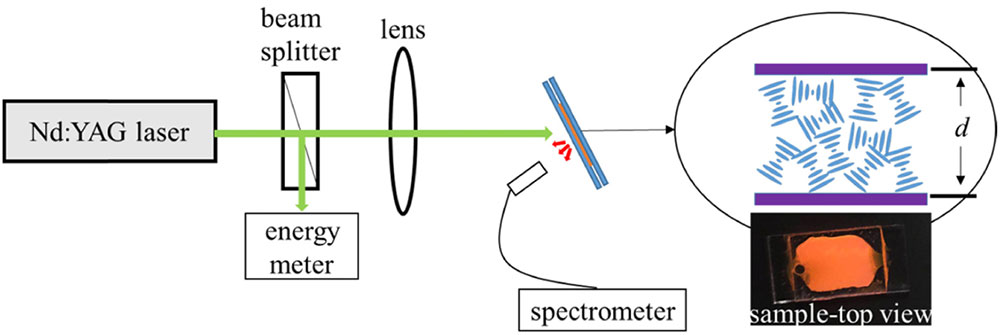
Figure 1.Sketch of the experimental setup.
3. RESULTS AND DISCUSSION
Dye-doped CLCs with different concentrations of the chiral agent have different selective reflection bands. The PBGs were characterized by measuring the reflection spectra using planarly oriented cells with a thickness of 7.7 μm. The planarly oriented CLC samples doped with wt.% (, 40.0, 38.0, 34.0, 32.0) of the chiral agent dopant CB15 are labeled as S1, S2, S3, S4, S5, respectively. The reflection characteristics for oriented cells with different chiral agent concentrations are shown in Fig. 2(a). The texture images shown in the insets were obtained by a polarization optical microscope (POM) operating in reflection mode. The texture color of the sample S1 is blue, whose selective reflection band is located on the left (shorter wavelength) side of the fluorescence peak of PM597. Samples S2 and S3 have a green appearance in POM, whose selective reflection bands considerably overlap with the fluorescence peak of the PM597. The selective reflection bands of the samples S4 and S5 are located on the right side (longer wavelength) of the fluorescence peak. The transmission spectra of different mixtures in oriented CLC cells are shown in Fig. 2(b). The dip at the wavelength of 532 nm in every transmission spectrum results from the absorption of the dye. The absorption also causes a deformation of the real long wavelength edge (LWE) of the sample S1 and a redshift of the real short wavelength edge (SWE) of the sample S2 in Fig. 2(a).

Figure 2.(a) Reflection spectra and (b) transmission spectra for dye-doped planarly oriented CLC samples with different concentrations of the chiral agent CB15. The black solid curve is the fluorescence spectrum of PM597.
Figure 3 shows the texture images of five disordered CLC samples in nonoriented cells. The randomly oriented CLC samples doped with wt.% (, 40.0, 38.0, 34.0, 32.0) of chiral dopant CB15 are labeled as S1*, S2*, S3*, S4*, S5*, respectively. The pictures in the first row show the textures captured by the POM in reflection mode. The corresponding textures captured in transmission mode are shown in the second row. In general, the helical pitch of CLCs depends mainly on the concentration of the chiral agent [33], and the pitch determines the reflective band. By comparing the textures in Figs. 3(a)–3(e), we found the colors of bright microdomains in random samples were nearly the same as observed in the corresponding planarly oriented samples. The helical axes of the bright CLC microdomains are oriented perpendicularly to the glass substrates, as in the oriented cells, which results in selective reflection into the field of view of the POM operating in reflection mode. The size of the CLC microdomains is about 5.0 μm in diameter, which can be estimated from the size of the bright microregions. The same observation method is always used in blue phase liquid crystal [34].
Figure 3.Texture patterns of samples with different concentrations of the chiral agent CB15 in nonoriented cells observed by a POM with a objective. (a) S1*, (b) S2*, (c) S3*, (d) S4*, (e) S5* in reflection mode. (f)–(j) Corresponding textures in transmission mode. All cell gaps are 230 μm.
Figure 4 shows the emission characteristics of samples with different concentrations of CB15 in the single shot regime. For sample S1*, there exists only an RL emission band within the spectra, as shown in Fig. 4(a). With the increase of the pump energy, many narrow peaks (linewidth ) emerge on the top of the fluorescence emission band, which is due to the feedback of multiple scattering from the randomly oriented microdomains. But, for sample S2* [Fig. 4(b)], besides the main RL emission band at 578 nm, another emission band with lots of narrow peaks (linewidth ) emerges around a central wavelength of 595 nm, which is the LWE BEL of the CLC structure. There is a possibility of BEL in single microdomains; however, RL will not appear due to the lack of multiple scattering. Moreover, if the thickness of the CLC helix structure is very small, the feedback from multiple internal reflections will not be enough to trigger the BEL. When the pump energy increases, this BEL appears slightly earlier than the RL. The helical pitch of different CLC microdomains fluctuates around the central value due to elastic distortions, which results in multimode BEL. Because the SWE of the CLC is almost located outside of the fluorescence emission band, only LWE-BEL modes appear. But, besides this, because the fluorescence peak of the laser dye situates within the selective reflection band, there exists an additional reflection process associated with the CLC microdomains. Therefore, the RL emission peaks are pronounced in the emission spectra for S2*.
Figure 4.Spectra (a)–(e) represent emission for different disordered samples S1*, S2*, S3*, S4*, S5*, respectively. (f) The dependence of the peak intensities of the random lasing on the pump energy for different concentrations of the chiral agent. The black lines in spectra (g)–(k) are the emission spectra corresponding to spectra (a)–(e); the red lines in spectra (g)–(k) are reflection spectra for oriented CLC samples, respectively.
As shown in Figs. 4(c) and 4(d), both multimode BEL and RL arise in samples S3* and S4*, too. In both cases, with the increase of pump energy, BEL appears slightly earlier than RL. Since both band edges are located inside the fluorescence emission band for sample S3*, there exists not only SWE-BEL but also LWE-BEL. But, for sample S4*, only the SWE is located in the fluorescence emission band, which causes only an SWE-BEL emission band. From the spectra in Figs. 4(b)–4(d), one can see that the BEL emission band shifts with the shift of the bandgap. The fluorescence peak of sample S3* also coincides with its selective reflection band, similar to that of sample S2*. Therefore, enhancement of the feedback originating from selective reflection, as described above, is expected in this sample as well. For sample S4*, its bandgap moves out of the fluorescence peak, just like for sample S1*, which makes the feedback for the RL weaker. In the case of sample S5*, the bandgap moves farther out of the fluorescence emission band. Consequently, only one emission band, with many small and narrow peaks on the top, is observed.
Figure 4 clearly shows the evolution of the emission of the disordered CLC samples with different concentrations of chiral agents. The BEL emission band shifts with the change of the bandgap, while the RL emission band remains practically constant. We further measured the emission spectra for different positions and different single-pump shots of the sample S2*. As shown in Fig. 5, the RL peaks are stochastic and vary from position to position and from shot to shot. These phenomena are common in random lasing experiments, as different spatial modes are excited at different locations or at different times. In other words, the RL modes have statistical fluctuation properties, e.g., distribution of their frequencies, intensities, etc.
Figure 5.(a) Emission spectra for different pump positions across the sample S2*. (b) Emission spectra of the sample S2* for different single-pump shots.
As shown in Figs. 4(h) and 4(i), the selective reflection bands of the samples S2* and S3* considerably overlap with the fluorescence peak of the dye. In general, as with 1D photonic crystals, the CLCs have PBGs for the normally or obliquely incident light. In the range of the selective reflective band of CLCs, the scattering of normally or obliquely incident light in the direction of reflection is strong. Namely, the CLC domains designated by red arrows in Fig. 6(a) exhibit strong scattering due to the selective reflection, which causes more light energy to return to the loop rather than dissipate outside the loop. As a result, the dwell time of the light at the fluorescence peak increases in the random system. Due to this, the feedback effect of the multiscattering at the peak of fluorescence emission is strongly enhanced. Consequently, the threshold for random lasing is decreased. Therefore, according to the above proposed working mechanism, the RL thresholds of samples S2* and S3* should be significantly lower than that of samples S4* and S5*. Meanwhile, the random lasing spikes are more prominent.
Figure 6.Working mechanism of RL in a dye-doped CLC random system with a selective reflection band (a) coinciding with the fluorescence peak and (b) far away from the fluorescence peak. The yellow arrows represent the scattering light beams at the wavelength of the fluorescent peak. The helical axes of microdomains designated by red arrows exhibit a small angle with the direction of the incident light, which results in enhanced reflective behavior when the selective reflection band of the sample overlaps with the fluorescence peak of the dye. The dark and light yellow arrows represent strong and weak feedback, respectively.
For the samples S4* and S5*, their selective reflection bands move out of the fluorescence peak, which makes the feedback of multiscattering weaker, as shown in Fig. 6(b). Therefore, the RL thresholds for those samples are expected to become higher. The feedback is the smallest for sample S5* due to its bandgap moving away from the fluorescence peak, which results in the highest threshold.
According to Fig. 4(f), the corresponding RL thresholds observed in our experiments are about 2.7, 1.5, 2.6, 3.6, and 4.3 μJ for the five randomly oriented samples, respectively. In Ref. [35], a higher spectral peak and a larger slope efficiency can be partly attributed to the mode selection properties of the bubble structure in a diffusion system, while in our disordered CLC system the enhancement of RL is attributed to the selective reflection band of CLCs. Nevertheless, one still may wonder about the origin of the relatively large difference between the RL thresholds of the samples S2* and S3*. It is known that, when the band edge of the CLC structure lays within the absorption band, anomalously strong absorption takes place at the band edge [36]. The DOS and photon dwell time of the light at the band edge are greatly enhanced due to the multiple internal reflections of the CLC. In such a case, the excitation of dye molecules will be strongly enhanced when the sample is excited by pump light with a wavelength at the band edge. This effect has been used to achieve low threshold and high-efficiency BEL [37]. The LWE of sample S1* and the SWE of sample S2* are located just in the absorption band of the dye and around the pump wavelength. When samples S1* and S2* are excited at a wavelength of 532 nm, as in Figs. 4(g) and 4(h), the RL feedback is additionally enhanced due to the enhanced excitation of dye molecules. As a consequence, the RL threshold of the sample S1* is lower than that of the samples S4* and S5*, although its bandgap moves away from the fluorescence peak. Sample S2* has the lowest RL threshold because not only does its CLC selective reflection band overlap with the fluorescence peak of the dye molecules, its SWE also coincides with the excitation wavelength.
4. CONCLUSIONS
Our results demonstrate that random lasing in strongly disordered dye-doped CLCs with different bandgaps exhibits an intriguing cooperative effect between selective reflection associated with CLC domains and random scattering related to the random orientation of helical axes in these domains. Emission properties of the medium change with the shift of the bandgap. Besides random lasing, multimode BEL may appear, which results from the variation of the helical pitch in various CLC domains. We have shown that the RL threshold is reduced for the compositions whose fluorescence peak is located within the selective reflection band. This is due to the feedback enhancement of multiple scattering for the light of the fluorescence peak via the selective reflection process. Moreover, the threshold of random lasing is further decreased if the band edge also lays within the absorption band of the dye molecules and coincides at the same time with the excitation wavelength. These findings open a pathway toward optimization of CLC media for application in random lasing systems and, consequently, broaden a range of their possible exploration in photonics research and technologies.
References
[1] V. S. Letokhov. Generation of light by a scattering medium with negative resonance absorption. J. Exp. Theor. Phys., 26, 835-840(1968).
[2] N. M. Lawandy, R. M. Balachandran, A. S. L. Gomes, E. Sauvain. Laser action in strongly scattering media. Nature, 368, 436-438(1994).
[3] W. L. Sha, C. H. Liu, R. R. Alfano. Spectral and temporal measurements of laser action of Rhodamine 640 dye in strongly scattering media. Opt. Lett., 19, 1922-1924(1994).
[4] M. A. Noginov, H. J. Caulfield, N. E. Noginova, P. Venkateswarlu. Line narrowing in the dye solution with scattering centers. Opt. Commun., 118, 430-437(1995).
[5] G. Van Soest, M. Tomita, A. Lagendijk. Amplifying volume in scattering media. Opt. Lett., 24, 306-308(1999).
[6] G. van Soest, F. J. Poelwijk, R. Sprik, A. Lagendijk. Dynamics of a random laser above threshold. Phys. Rev. Lett., 86, 1522-1525(2001).
[7] D. S. Wiersma, A. Lagendijk. Light diffusion with gain and random lasers. Phys. Rev. E, 54, 4256-4265(1996).
[8] H. Cao, Y. G. Zhao, S. T. Ho, E. W. Seelig, Q. H. Wang, R. P. H. Chang. Random laser action in semiconductor powder. Phys. Rev. Lett., 82, 2278-2281(1999).
[9] H. Cao, J. Y. Xu, D. Z. Zhang, S. Chang, S. T. Ho, E. W. Seelig, X. Liu, R. P. Chang. Spatial confinement of laser light in active random media. Phys. Rev. Lett., 84, 5584-5587(2000).
[10] H. Cao, J. Y. Xu, Y. Ling, A. L. Burin, E. W. Seeling, X. Liu, R. P. Chang. Random lasers with coherent feedback. IEEE J. Sel. Top. Quantum Electron., 9, 111-119(2003).
[11] S. F. Yu, C. Yuen, S. P. Lau, W. I. Park, G. C. Yi. Random laser action in ZnO nanorod arrays embedded in ZnO epilayers. Appl. Phys. Lett., 84, 3241-3243(2004).
[12] S. Mujumdar, M. Ricci, R. Torre, D. S. Wiersma. Amplified extended modes in random lasers. Phys. Rev. Lett., 93, 053903(2004).
[13] L. Sznitko, J. Mysliwiec, A. Miniewicz. The role of polymers in random lasing. J. Polym. Sci. Part B: Polym. Phys., 53, 951-974(2015).
[14] G. Strangi, S. Ferjani, V. Barna, A. De Luca, C. Versace, N. Scaramuzza, R. Bartolino. Random lasing and weak localization of light in dye-doped nematic liquid crystals. Opt. Express, 14, 7737-7744(2006).
[15] A. K. Tiwari, S. Mujumdar. Random lasing over gap states from a quasi-one-dimensional amplifying periodic-on-average random superlattice. Phys. Rev. Lett., 111, 233903(2013).
[16] J. P. Dowling, M. Scalora, M. J. Bloemer, C. M. Bowden. The photonic band edge laser: a new approach to gain enhancement. J. Appl. Phys., 75, 1896-1899(1994).
[17] V. I. Kopp, Z. Q. Zhang, A. Z. Genack. Lasing in chiral photonic structures. Prog. Quantum Electron., 27, 369-416(2003).
[18] S. Furumi, S. Yokoyama, A. Otomo, S. Mashiko. Electrical control of the structure and lasing in chiral photonic band-gap liquid crystals. Appl. Phys. Lett., 82, 16-18(2003).
[19] P. V. Shibaev, R. L. Sanford, D. Chiappetta, V. Milner, A. Genack, A. Bobrovsky. Light controllable tuning and switching of lasing in chiral liquid crystals. Opt. Express, 13, 2358-2363(2005).
[20] S. M. Morris, A. D. Ford, M. N. Pivnenko, H. J. Coles. Enhanced emission from liquid-crystal lasers. J. Appl. Phys., 97, 023103(2005).
[21] H. Finkelmann. Tunable mirrorless lasing in cholesteric liquid crystalline elastomers. Adv. Mater., 13, 1069-1072(2010).
[22] Y. Huang, Y. Zhou, Q. Hong, A. Rapaport, M. Bass, S. T. Wu. Incident angle and polarization effects on the dye-doped cholesteric liquid crystal laser. Opt. Commun., 261, 91-96(2006).
[23] C. T. Wang, C. W. Chen, T. H. Yang, I. Nys, C. C. Li, T. H. Lin, K. Neyts, J. Beeckman. Electrically assisted bandedge mode selection of photonic crystal lasing in chiral nematic liquid crystals. Appl. Phys. Lett., 112, 043301(2018).
[24] Y. Zhou, Y. Huang, A. Rapaport, M. Bass, S. T. Wu. Doubling the optical efficiency of a chiral liquid crystal laser using a reflector. Appl. Phys. Lett., 87, 231107(2005).
[25] Y. Zhou, Y. Huang, S. T. Wu. Enhancing cholesteric liquid crystal laser performance using a cholesteric reflector. Opt. Express, 14, 3906-3916(2006).
[26] B. He, Q. Liao, Y. Huang. Random lasing in a dye doped cholesteric liquid crystal polymer solution. Opt. Mater., 31, 375-379(2008).
[27] S. M. Morris, D. J. Gardiner, P. J. Hands, M. M. Qasim, T. D. Wilkinson, I. H. White, H. J. Coles. Electrically switchable random to photonic band-edge laser emission in chiral nematic liquid crystals. Appl. Phys. Lett., 100, 071110(2012).
[28] P. J. W. Hands, D. J. Gardiner, S. M. Morris, C. Mowatt, T. D. Wilkinson, H. J. Coles. Band-edge and random lasing in paintable liquid crystal emulsions. Appl. Phys. Lett., 98, 141102(2011).
[29] L. Ye, Y. Wang, Y. Feng, B. Liu, B. Gu, Y. Cui, Y. Lu. Thermally switchable photonic band-edge to random laser emission in dye-doped cholesteric liquid crystals. Laser Phys. Lett., 15, 035002(2018).
[30] L. Li, L. Deng. Low threshold and coherent random lasing from dye-doped cholesteric liquid crystals using oriented cells. Laser Phys., 23, 085001(2013).
[31] L. W. Li, L. G. Deng. Random lasing from dye-doped chiral nematic liquid crystals in oriented and non-oriented cells. Eur. Phys. J. B, 86, 112(2013).
[32] H. Lu, J. Xing, C. Wei, J. Xia, J. Sha, Y. Ding, G. Zhang, K. Xie, L. Qiu, Z. Hu. Band-gap-tailored random laser. Photon. Res., 6, 390-395(2018).
[33] P. G. de Gennes, J. Prost. The Physics of Liquid Crystals, 6(1993).
[34] C. W. Chen, H. C. Jau, C. T. Wang, C. H. Lee, I. C. Khoo, T. H. Lin. Random lasing in blue phase liquid crystals. Opt. Express, 20, 23978-23984(2012).
[35] T. Okamoto, R. Yoshitome. Random lasing in dye-doped polymer random media with a bubble structure. J. Opt. Soc. Am. B, 34, 1497-1502(2017).
[36] V. A. Belyakov. Low threshold DFB lasing in chiral LC at diffraction of pumping wave. Mol. Cryst. Liq. Cryst., 453, 43-69(2006).
[37] Y. Matsuhisa, Y. Huang, Y. Zhou, S. T. Wu, R. Ozaki, Y. Takao, A. Fujii, M. Ozaki. Low-threshold and high efficiency lasing upon band-edge excitation in a cholesteric liquid crystal. Appl. Phys. Lett., 90, 091114(2007).


