• Chinese Optics Letters
  • Vol. 14, Issue 11, 112303 (2016)
Ping Ma1, Xuecheng Cui1, Jun Zheng2、3, Pinchun Kang4, and 志成 叶1、5、*
Author Affiliations
  • 1National Engineering Laboratory for TFT-LCD Technology, Department of Electrical Engineering, Shanghai Jiao Tong University, Shanghai 200240, China
  • 2Key Laboratory for Laser Plasmas (Ministry of Education) and Department of Physics and Astronomy, Shanghai Jiao Tong University, Shanghai 200240, China
  • 3Collaborative Innovation Center of IFSA (CICIFSA), Shanghai Jiao Tong University, Shanghai 200240, China
  • 4Department of Xiamen Institute of Measurement and Testing, Xiamen 361000, China
  • 5State Key Laboratory on Integrated Optoelectronics, Institute of Semiconductors, Chinese Academy of Sciences, Beijing 100083, China
  • show less
    DOI: 10.3788/COL201614.112303 Cite this Article Set citation alerts
    Ping Ma, Xuecheng Cui, Jun Zheng, Pinchun Kang, 志成 叶. Slim OFRS based on a grating input coupler and a microprism sensing surface[J]. Chinese Optics Letters, 2016, 14(11): 112303 Copy Citation Text show less
    Geometry of the planar waveguide with the microprism array. L0, L1, L2, and L3 are the length of the total OFRS, grating, microprism array, and width of detector; h is the thickness of the planar waveguide; n0 and n1 are the refractive indices of the circumstance medium (air) and the optical waveguide, respectively; d is the width of the single microprism; and θ1 and θ2 are the slope angles of the two facets s1 and s2, respectively.
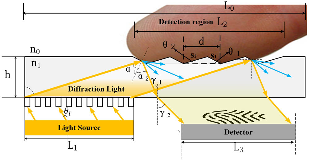
    Fig. 1. Geometry of the planar waveguide with the microprism array. L0, L1, L2, and L3 are the length of the total OFRS, grating, microprism array, and width of detector; h is the thickness of the planar waveguide; n0 and n1 are the refractive indices of the circumstance medium (air) and the optical waveguide, respectively; d is the width of the single microprism; and θ1 and θ2 are the slope angles of the two facets s1 and s2, respectively.
    Simulation model of a metallic grating. (a) 3D vision and (b) 2D vision of the front view. PR is photoresist (ARP 3500-6, Allresisit Co.). The symbols h2 and h1 represent the height of the grating and metal; θs represents the slant angle of the grating; Lu and Ld are the up and down length of the grating.
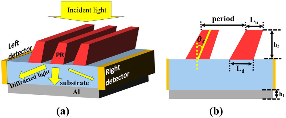
    Fig. 2. Simulation model of a metallic grating. (a) 3D vision and (b) 2D vision of the front view. PR is photoresist (ARP 3500-6, Allresisit Co.). The symbols h2 and h1 represent the height of the grating and metal; θs represents the slant angle of the grating; Lu and Ld are the up and down length of the grating.
    −1st order diffraction efficiency spectra of TE and TM polarized light with different parameters. Spectra of (a) TE and (b) TM polarized light with parameters: dc=0.58; h2=370 nm; θs=0∼30°; and ΔL=0. Spectra of (c) TE and (d) TM polarized light with θs=25° in (a) and (b).
    Fig. 3. 1st order diffraction efficiency spectra of TE and TM polarized light with different parameters. Spectra of (a) TE and (b) TM polarized light with parameters: dc=0.58; h2=370nm; θs=030°; and ΔL=0. Spectra of (c) TE and (d) TM polarized light with θs=25° in (a) and (b).
    Fingerprint images from the detector under prism angles θ=25° and 40° while θ1=1° and d=0.05 mm.
    Fig. 4. Fingerprint images from the detector under prism angles θ=25° and 40° while θ1=1° and d=0.05mm.
    (a) The light paths for different values of θ2, (b) the fingerprint images from the detector under θ2=0.5°, 1°, and 35° while d=0.05 mm and θ1=25°.
    Fig. 5. (a) The light paths for different values of θ2, (b) the fingerprint images from the detector under θ2=0.5°, 1°, and 35° while d=0.05mm and θ1=25°.
    Fingerprint images from the detector under different widths 0.05, 0.07, and 0.1 mm, of a single microprism.
    Fig. 6. Fingerprint images from the detector under different widths 0.05, 0.07, and 0.1 mm, of a single microprism.
    Fingerprint images from the detector under different divergent angles of light source, with θ1=25°, θ2=1°, and d=0.05 mm.
    Fig. 7. Fingerprint images from the detector under different divergent angles of light source, with θ1=25°, θ2=1°, and d=0.05mm.
    Profile of the microprism with: (a) ideal angle and non-gap; (b) non-sharp vertex angle and a small gap between two adjacent microprisms. Fingerprint images from two sensors while the microprisms are not ideal: (c) the corner radius is 0.01 mm and (d) the distance between two microprisms is 0.03 mm.
    Fig. 8. Profile of the microprism with: (a) ideal angle and non-gap; (b) non-sharp vertex angle and a small gap between two adjacent microprisms. Fingerprint images from two sensors while the microprisms are not ideal: (c) the corner radius is 0.01 mm and (d) the distance between two microprisms is 0.03 mm.
    Ping Ma, Xuecheng Cui, Jun Zheng, Pinchun Kang, 志成 叶. Slim OFRS based on a grating input coupler and a microprism sensing surface[J]. Chinese Optics Letters, 2016, 14(11): 112303
    Download Citation