
Jiyu Pan, Shuiqiang Zhang, Zhilong Su, Shen Wu, Dongsheng Zhang. Measuring Three-Dimensional Deformation of Underwater Propellers Based on Digital Image Correlation[J]. Acta Optica Sinica, 2021, 41(12): 1212001
- Acta Optica Sinica
- Vol. 41, Issue 12, 1212001 (2021)
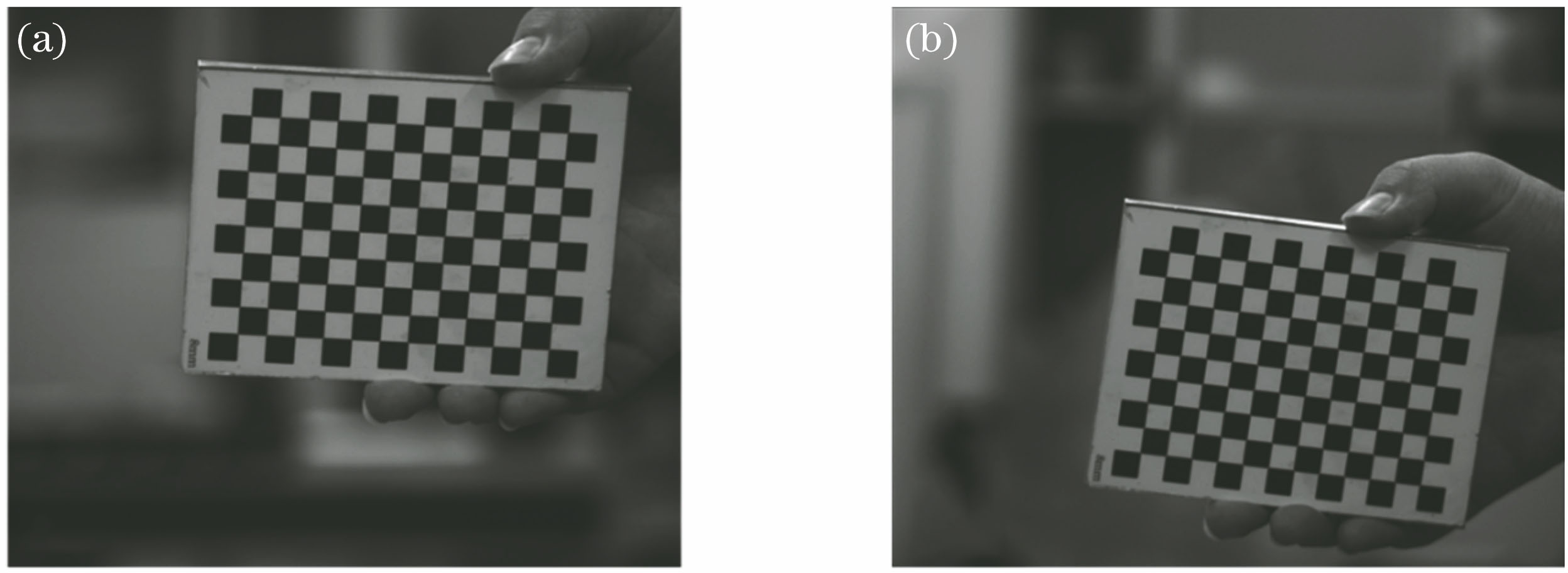
Fig. 1. Chessboard images of different cameras. (a) Camera C0; (b) camera C1
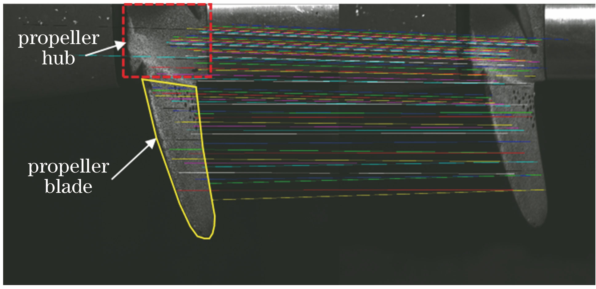
Fig. 2. Feature matching results in external parameter calibration
Fig. 3. Image matching and reconstruction in 3D-DIC measurement
Fig. 4. Schematic diagram of rigid body displacement caused by the rotation of the propeller hub
Fig. 5. Schematic diagram of the refraction light path
Fig. 6. Displacement results calculated by two methods. (a) Displacement; (b) difference between the measured value and the true value
Fig. 7. Stereo vision measurement system. (a) Diagram of the experimental setup; (b) image observed by camera C0 ; (c) image observed by camera C1
Fig. 8. Three-dimensional topographies of the cylindrical surface before and after refraction correction
Fig. 9. Physical image of the 3D-DIC measurement system
Fig. 10. Images observed by two cameras. (a) Camera C0; (b) camera C1
Fig. 11. Displacement fields in different directions when the water velocity is 2 m/s
Fig. 12. Displacement fields in different directions when the water velocity is 3 m/s
|
Table 1. Internal parameters of the camera
|
Table 2. External parameters between cameras

Set citation alerts for the article
Please enter your email address
© Copyright 2018-2021 | Chinese Laser Press. All Rights Reserved 沪ICP备15018463号-20