Abstract
The excitation of high-order Laguerre–Gaussian (LG) modes in a neodymium-doped yttrium aluminum garnet (Nd:YAG) laser resonator was presented by applying the diffraction of a second-order circular Dammann grating (CDG) for annular pumping. In the study, the 808 nm pump light was shaped into a double-ring structure by the CDG and matched spatially with that of an ideal LG11 mode. As a result, the laser resonator generated an LG11 vortex mode, and the laser power reached 204 mW with 14.5% slope efficiency. Also, when the cavity mirror was tilted, the laser output could switch to the LG01 vortex mode. The results showed the convenience and versatility of CDG in an annular-pumped vortex laser.Laguerre–Gaussian (LG) modes, which are one set of eigen solutions of the Helmholtz equation under paraxial approximation in the cylindrical coordinate, exhibit doughnut-like transversal intensity distribution and possess a helical phase wave-front[1]. Generally, LG modes are described by , where and are the radial and azimuthal indices[2]. modes with have rings in the transverse field, and a helical phase front with topological charge of carries a component of orbital angular momentum (OAM) of per photon[3]. That is why LG modes are also called optical vortex beams[4]. Based on those physical properties, LG beams have been widely used in optical manipulation[5], optical communication in free space[6], super resolution microscopy[7], optical switching[8], and spinning object detection[9,10]. Compared with lower-order LG modes, high-order modes show superior performance in some fields[11,12]. For example, the high-order mode reduces the thermal noise of the mirrors, and its presence in the application of gravitational-wave detection signifies high sensitivity and a high detection rate[13–15].
The methods for generating LG modes include passive and active ways. The former refers to the spatial conversion of an incoming light beam after transmitting through the optical elements, like computed holograms[16], spiral phase plate[17], and spatial light modulator[18]. The latter aims to the direct oscillation of the desired LG mode in a laser resonator, either by deploying various mode selectors inside it[19] or applying the annular pumping technique[20–23]. As the annular pumping profile, after some shaping optics, intrinsically has good spatial overlapping with target LG modes in the gain medium, this technique favors the LG-mode excitation of one laser resonator with high efficiency and high modal purity.
As is known, a circular Dammann grating (CDG), a binary-phase component with periodic and alternate 0 and π phases in the radial direction, can diffract an incoming light into a single ring or multiple concentric rings with equal intensities at the far field[24,25]. We previously reported the utilization of a first-order CDG to implement a single-ring-pumped -mode neodymium-doped yttrium aluminum garnet (Nd:YAG) laser. This scheme is easy to realize by only inserting the CDG element into the laser’s pump unit, and also, the fabrication of these elements is simple and with low cost.
Sign up for Chinese Optics Letters TOC. Get the latest issue of Chinese Optics Letters delivered right to you!Sign up now
In this study, to test the CDG’s ability in assisting the excitation of high-order vortex mode, we firstly applied a second-order CDG to shape the pump light into a double-ring intensity profile at the far field; thereafter, we demonstrated the mode’s oscillation of a Nd:YAG laser. Furthermore, the mode’s oscillation was switched to the mode stably when we slightly adjusted the inclination of the output coupler (OC) of the laser. The results showed the versatility of CDG-based annular pumping for a high-order LG-mode vortex solid-state laser.
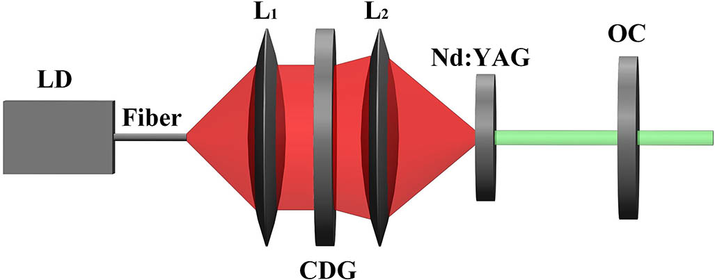
Figure 1 shows the schematic diagram of the laser. An 808 nm fiber-coupled laser diode was used as the pump source, and its tail fiber had a core diameter of 105 μm and numerical aperture of 0.22. Behind the pigtail fiber, two lenses and , with the focal lengths of 15 and 25.4 mm, respectively, were used to collimate the pump radiation and then focus it into the gain medium. The gain medium was a piece of Nd:YAG crystal that had 1 at. % doping concentration of Nd ions, 10 mm diameter, and 1 mm thickness. The front surface of it was coated for high transmission at 808 nm and high reflection at 1064 nm, and its rear surface was anti-reflection coated at 1064 nm. Both surfaces of the crystal clung to two large copper plates for cooling. In the central part of each copper plate, there was a 5 mm diameter hole drilled for light propagation. Further, a plane mirror with a transmittance of 2% at 1064 nm was placed behind the Nd:YAG crystal as an OC, and the distance between it and front surface of the crystal was 10 mm.

Figure 1.Schematic diagram of an end-pumped laser involving a CDG in the pumping unit.
Except for the above-mentioned arrangement, a second-order CDG was placed between lenses and . This CDG had a 25 mm clear aperture and was wet-etched on a substrate of BK7 glass in the form of concentric grooves with a 53.87 μm radial period and 790 nm depth. Figure 2(a) shows the surface view of the applied CDG taken by microscopy, in which the concentric and periodic structures were used to partition the profile of an incident pump beam and induce the periodic 0 and π phase shifts along the radial direction. Figure 2(c) plots the detailed structure of the CDG’s cross section schematically along radial direction. As seen, three sets of combinations of the ridges and grooves existed alternately in each period, and the theoretical widths of them were variable with the values of , , , , , and , respectively. With these parameters, this CDG would diffract only the first- and third-order pump light beams at 15 and 45 mrad diffraction angles with a theoretical diffraction efficiency of 80%.
Figure 2.(a) Top view of second-order CDG taken by microscopy, where the bright rings indicate the ridges, and the dark ones represent the grooves, (b) transverse intensity distribution of diffracted pump light at the far field, (c) schematic cross section of the CDG along the radial direction, and (d) the line profile of pump light along the radial direction.
The captured intensity distribution, as well as the corresponding line profile, of the pump light at the focus of is shown in Figs. 2(b) and 2(d). As observed, except for zero-order transmission, both the first- and third-order diffraction rings appeared at the far field with 406 μm and 1.23 mm ring radius, as well as 135 and 141 μm full width at half-maximum (FWHM), respectively. Therefore, the radius ratio of the outer and inner diffraction rings of pump light covered the range between and , i.e., 3.84 and 2.45. Further, the radius ratio of the outer and inner rings of an ideal mode is nearly 3.21, which fell exactly in the range of the radius ratio of the pump diffraction rings, and thus, it had a good spatial match with the pump light field inside the resonator.
After the diffracted pump light was projected to the Nd:YAG laser crystal, the resonator cavity consisting of an OC and front surface of a laser crystal was optimized and began to oscillate at the pump level above the threshold. As shown in Fig. 3, when the absorbed pump power () was larger than 1.02 W, the output power of the laser increased linearly with a slope efficiency of 14.5% and reached 204 mW at .
Figure 3.Variation of output power of the laser with pump power.
The intensity distribution of laser beams varied with pump power. Figure 4 depicted the captured intensity profiles of the laser beam at different pump powers.
Figure 4.Intensity distributions of double-ring modes obtained at different pump powers: (a) , (b) , (c) , (d) , (e) , (f) , (g) , and (h) .
As shown in Fig. 4(a), at , where the pump power was a little higher than the threshold, the laser produced a fundamental transverse electromagnetic ()-like mode. When the pump power increased and was smaller than 1.45 W, the laser showed the tendency to oscillate in the single-ring mode, as shown in Fig. 4(b). When was larger than 1.45 W, the double-ring structure of the laser mode appeared, with an obvious central null intensity, and such a shape was well-maintained in the range of . Further, when the pump power exceeded the level of , the double-ring structure of the laser beam remained, and additionally, the central null intensity of it was lightened. The difference between the output mode in Fig. 4(h) and the others could be attributed to the excitation of the mode induced by the zero-order diffraction.
Then, the laser mode that had the double-ring intensity profile was analyzed. Figure 5 plots a one-dimensional intensity distribution of the laser mode obtained at . Simultaneously, this measured line intensity profile was also fitted by using a linear superposition of a Laguerre-polynomial-modulated Gaussian function with the order of (where and ) and a Gaussian function. As seen, the experimental curve agreed well with the theoretical profile of linear superposition of and modes. Correspondingly, the output power shown in Fig. 3 included both and modes, which meant that the actual output power of the mode was lower than experimental results. This comparison suggested that the intensity distribution of the obtained double-ring mode of the laser was principally made up of an ideal mode. Moreover, the existence of the mode was associated with the excitation induced by zero-order diffraction of second-order CDG, which was caused by the error of etching depth during fabrication. Therefore, the fraction of the mode could be reduced by diminishing the error of absolute depth and improving the uniformity of etching depth in the grating plane to eliminate the zero-order diffraction of CDG. It means that it is possible to generate the pure mode with the well-fabricated second-order CDG.
Figure 5.Measured and theoretical intensity distribution of the laser mode along the horizontal direction at . The black triangles represent the measured data points of the double-ring mode, the red line represents the theoretical profile of linear superposition of the and modes, and the green and blue dashed lines represent the respective intensity profiles of theoretical and modes.
Furthermore, the propagation behavior of the obtained double-ring mode was evaluated. Figure 6 depicts the variation of its waist diameter with propagation distance after the laser beam passed through a focusing lens. According to these curves, the quality factors square () were calculated to be 4.42 in the direction and 4.41 in the direction, and these data were close to 4 for an ideal mode.
Figure 6.Evolution of beam waist of the laser mode at along propagation distance. , quality factors square.
Finally, the interferometric technique was used to detect the phase of the obtained double-ring laser mode. Figure 7 shows the schematic setup of a Mach–Zehnder (M-Z) interferometer. The laser beam from the resonator was divided into two beams by a non-polarized beam splitter (NPBS). The beam in the upper arm was clipped by a 150 μm diameter pinhole, and then, the clipped fraction of the laser beam was collimated and acted as the plane reference wave. The laser beam in the lower arm was attenuated and acted as the signal wave. Both the reference beam and signal beam were directed into a charge-coupled device (CCD) camera, and Fig. 8 plots the measured interference pattern of them at .
Figure 7.Schematic diagram of the Mach–Zehnder interferometer for phase detection. NPBS, non-polarized beam splitter.
Figure 8.Captured interference patterns of the double-ring mode at .
Theoretically, when the plane vortex beam and plane wave interferes, the Y-shaped fork would be formed near the phase singularity, and the numbers of the fork stand for the numbers of topological charge embodied in the helical phase. According to the interference pattern depicted in Fig. 8, the number difference between the upper and lower sides of the outer interference stripes, as well as the number difference between the upper and lower sides of the inner interference stripes, was one. Therefore, it could be inferred that both inner and outer rings of the double-ring laser mode had helical phases with respective topological charges of one, i.e., the double-ring laser mode from the resonator was the mode when was in the range of 1.45 to 2.11 W.
In our experiment, it was found that the double-ring laser mode could be switched to a single-ring mode when tilting the OC to a specific angle. Furthermore, single-ring-mode operation of the laser was stable, and the switching between double- and single-ring modes was producible. Figure 9 depicts the variation of output power with pump power when the laser was operated in the single-ring mode. As seen, at this time, this laser had the threshold pump power of , and the output power increased linearly with at a slope efficiency of 14.7% and reached its maximum of 77 mW at . The intensity distributions of the laser mode at different pump power were shown in Fig. 10. As seen, the laser beam was at the mode at low pump power close to the threshold and transformed into the single-ring mode at . Further, the single-ring intensity distribution of the laser mode maintained until reached 1.71 W. When exceeded 1.71 W, the axis symmetry of the single-ring mode started to deteriorate, and its shape tended to be irregular.
Figure 9.Variation of output power of the laser with pump power.
Figure 10.Intensity distributions of single-ring modes obtained at different pump powers: (a) , (b) , (c) , (d) , and (e) .
Then, the measured intensity distribution of the single-ring mode along the horizontal direction at was fitted by a Laguerre-polynomial-modulated Gaussian function with the order of (where and ). As shown in Fig. 11, the measured curve had a great agreement with their respective theoretical data, and this comparison suggested the intensity distribution of the obtained single-ring mode of the laser was identical to that of an ideal mode. Also, the evolution of beam waist diameter along propagation distance was measured at and shown in Fig. 12. The beam quality factor was measured to be 2.41 in the direction and 2.10 in the direction, and these data were close to 2 for an ideal mode. Furthermore, the M-Z interferometer was used to detect the phase structure of the obtained single-ring mode, and the interference patterns are shown in Fig. 13. The Y-shaped structure in the central region indicated that the single-ring mode from the Nd:YAG laser resonator had a helical phase with a topological charge of one, i.e., the single-ring laser mode from the resonator was the mode when was in the range of 1.41 to 1.71 W.
Figure 11.Measured and theoretical intensity distribution of the laser mode along the horizontal direction at .
Figure 12.Evolution of the beam waist of the laser mode at along the propagation distance.
Figure 13.Captured interference patterns of the single-ring mode at .
In the experiment, with an optimized parallel cavity structure, the resonator generated the double-ring mode, while with tilted OC, the laser emitted the single-ring mode. Such a mode switching phenomenon was associated with the variation of intracavity mode loss.
As known, both and modes are eigen modes of the circular mirror cavity. In the resonator with a parallel cavity, the intracavity losses of both modes were at a relatively low level. In the optimized parallel cavity, the mode had the highest spatial overlapping efficiency with pump light field, and it could extract most of stored gain and thus dominated in the mode competition. As a result, the parallel cavity laser resonator emitted the mode when was in the range of 1.45 to 2.11 W. Compared with the low-order mode, the mode had a much larger divergence angle, and therefore, the diffraction loss of it increased rapidly with the tilt angle of the OC. Although the mode had relatively lower spatial overlapping efficiency with the double-ring pump light field, it became dominated in mode competition because of its low diffraction loss when the OC was tilted. As a result, the laser emission switched to the mode when was in the range between 1.41 and 1.71 W, and the corresponding power of the mode was lower than the case of -mode operation, owing to the increase of the total intracavity loss.
Although the mode was obtained in lasers with first- and second-order CDG by annual pumping, we think there are some differences in principle. The mode was generated from the laser with first-order CDG for its high spatial overlapping efficiency, while it was generated from the laser with second-order CDG and tilted OC for its low diffraction loss.
In summary, we proposed an -mode Nd:YAG laser by applying a second-order CDG to shape the pump light into a double-ring pump field, and the -mode power of the laser reached 204 mW with a slope efficiency of 14.5%. The further experiment showed that the -mode laser could be switched to the mode stably by slightly adjusting the tilt angle of the OC. The results showed the versatility of high-order CDG for an annular pumping high-order vortex-mode solid-state laser. The performance of our laser still had a large space to promote. Specifically, the diffraction efficiency of the used grating could be increased by applying anti-reflection coating, where the zero-order transmission of it could be eliminated by optimizing the fabrication, and the quality of the vortex laser mode at high pump power could be improved further by optimizing the cooling to the laser crystal.
References
[1] L. Allen, M. J. Padgett, M. Babiker. Prog. Opt., 39, 291(1999).
[2] X. Liu, T. Wu, L. Liu, C. Zhao, Y. Cai. Chin. Opt. Lett., 15, 030002(2017).
[3] L. Allen, M. W. Beijersbergen, R. J. C. Spreeuw, J. P. Woerdman. Phys. Rev. A, 45, 8185(1992).
[4] J. E. Curtis, D. G. Grier. Phys. Rev. Lett., 90, 133901(2003).
[5] D. G. Grier. Nature, 424, 810(2003).
[6] J. Wang. Photon. Res., 4, B14(2016).
[7] P. Torok, P. R. T. Munro. Opt. Express, 12, 3605(2004).
[8] A. E. Willner, L. Li, G. Xie, Y. Ren, H. Huang, Y. Yue, N. Ahmed, M. J. Willner, A. J. Willner, Y. Yan, Z. Zhao, Z. Wang, C. Liu, M. Tur, S. Ashrafi. Photon. Res., 4, B5(2016).
[9] M. P. J. Lavery, F. C. Speirits, S. M. Barnett, M. J. Padgett. Science, 341, 537(2013).
[10] G. Milione, T. Wang, J. Han, L. Bai. Chin. Opt. Lett., 15, 030012(2017).
[11] M. A. Clifford, J. Arlt, J. Courtial, K. Dholakia. Opt. Commun., 156, 300(1998).
[12] N. B. Simpson, L. Allen, M. J. Padgett. J. Mod. Opt., 43, 2485(1996).
[13] M. Granata, C. Buy, R. Ward, M. Barsuglia. Phys. Rev. Lett., 105, 231102(2010).
[14] P. Fulda, K. Kokeyama, S. Chelkowski, A. Freise. Phys. Rev. D, 82, 012002(2010).
[15] S. Chelkowski, S. Hild, A. Freise. Phys. Rev. D, 79, 122002(2009).
[16] N. R. Heckenberg, R. McDuff, C. P. Smith, A. G. White. Opt. Lett., 17, 221(1992).
[17] M. W. Beijersbergen, R. P. C. Coerwinkel, M. Kristensen, J. P. Woerdman. Opt. Commun., 112, 321(1994).
[18] N. Matsumoto, T. Ando, T. Inoue, Y. Ohtake, N. Fukuchi, T. Hara. J. Opt. Soc. Am. A, 25, 1642(2008).
[19] S. Tan, C. Zhou, A. Shirakakwa, K. Ueda, J. Li. Opt. Laser Technol., 96, 76(2017).
[20] Z. Fang, K. Xia, Y. Yao, J. Li. Appl. Phys. B, 117, 219(2014).
[21] J. Li, Y. Yao, J. Yu, K. Xia, C. Zhou. IEEE Photon. Technol. Lett., 28, 473(2016).
[22] Y. Xu, X. Han, G. Li, J. Liu, K. Xia, J. Li. Opt. Eng., 55, 056101(2016).
[23] Y. Wu, Z. Wang, S. Chen, A. Shirakwa, K. Ueda, J. Li. Laser Phys. Lett., 15, 055804(2018).
[24] C. Zhou, L. Liu. Appl. Opt., 34, 5961(1995).
[25] C. Zhou, J. Jia, L. Liu. Opt. Lett., 28, 2174(2003).