Abstract
This Letter proposes a scanned holographic display system that takes the advantage of a high-speed resonant scanner to augment a galvanometer and hence improves the opto-mechanical information distribution capabilities, thereby potentially achieving an increased image size and enlarged viewing angles.With the ability to provide all the necessary visual depth cues[1,2], three-dimensional (3D) holographic displays have the potential to be the ultimate 3D images displays, attracting research efforts in the past decades[3,4]. To deliver 3D images with depth cues, the system needs to provide enough information with sufficient bandwidth both optically and digitally, regardless of the optical system.
An example is illustrative of the requirements of a representative system. A phase-only hologram with a pixel pitch of 10 μm can project 3D images of extent with a viewing angle, assuming the wavelength is 633 nm (red light). The image size and the viewing angle are exchangeable, while their product is a constant because of the Lagrange invariant[5]. Having (fps) requires more than 17 Gpixels/sec. Note that shorter wavelengths, such as 520 nm (green) and 450 nm (blue), have smaller viewing angles than red light, so they require more bandwidths for the same visual range. Considering the necessary bits per pixel, which is expected to be 8 bits to meet the commercial graphic standard, the overall bandwidth will be more than 100 Gb/s. Furthermore, the size and the viewing angle of this example are smaller than what general applications need. It is likely that 1 Tb/s or more is necessary. Therefore, there is a need to develop high-bandwidth spatial light modulators (SLMs) to meet this requirement before a practical 3D holographic display is feasible.
When we consider high-bandwidth devices, they can be categorized into two types: a high space bandwidth product (SBP) with a typical video rate frame rate, and a typical video-resolution SBP with a high frame rate. In the former case, for example, if the SLM can be made up to with 60 fps, it can directly be used to support a holographic image of a large image size and a wide viewing angle. Unfortunately, this is not feasible due to practical issues, such as pixel uniformity and the control of electronic signaling. Digital micro-mirror devices (DMDs) are a good example of the latter case. To fully utilize its bandwidth for holographic applications, there is a need to distribute frames efficiently so information contributes to visual imagery rather than being wasted. For example, a DMD supporting a frame resolution with 22727 fps provides 17 Gpixels/sec. Distributing this information for holographic 3D images requires careful system integration and the appropriate hologram computation. Our previous works in coarse integral holography (CIH)[6] and layer-based algorithms[7] were trying to deal with these difficulties. The principles of CIH will be briefly introduced shortly. However, our previous implementation of a scanned CIH system was limited by the capability of the physical scanner. Therefore, this Letter proposes an approach to incorporate an auxiliary resonant scanner to expand the information distribution capability of the scanned CIH system. It will be introduced later.
Sign up for Chinese Optics Letters TOC. Get the latest issue of Chinese Optics Letters delivered right to you!Sign up now
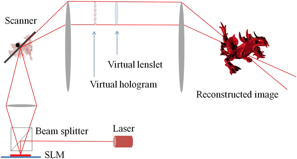
Coarse integral imaging[8,9] is a technique to angularly tile two-dimensional (2D) images to generate multiple 2D views. CIH takes advantage of this concept and replaces the 2D image sources with holograms carrying 3D image information[6]. CIH further takes advantages of holograms to integrate the phase profile of the lenslet of the lens array used in coarse integral imaging into hologram calculations so the overall system is simpler and easier to implement. Figure 1 illustrates the scanned CIH concept. The previous prototype demonstrated a full-color, full-parallax, 23.33-fps holographic video of a modest horizontal and small vertical viewing angle, although it only uses around half the bandwidth on the 1024 × 768 DMD with the maximum 22727 fps. Systems using scanners to distribute information from binary SLMs can also be found in Refs. [10,11].

Figure 1.Illustration of the CIH system.
The scanned CIH architecture could not use the full bandwidth of the DMD because of the limited scanning speed of the galvanometer. One possible approach to improve it is to replace the mirror substrate (aluminum on the current scanner) with a material with a higher strength-to-weight ratio, such as beryllium, so the mirror can sustain a higher scanning speed without being broken. However, a mirror substrate with that specific material is significantly more expensive.
To more clearly explain the limitation, we explain the scanning mechanism and define the scanning capability. CIH angularly tiles the holographic images, and each sub-hologram provides a small viewing angle of the target 3D images/scene (horizontally and vertically), say, . Adjacent sub-holograms should be projected at an adjacent view away from the previous view. The CIH scanning pattern is designed as shown in the left part of Fig. 2 so each frame has a horizontal viewing angle of and a vertical viewing angle of , where is the number of views in each scanline, and is the number of scanlines. Note that the scanning is continuous, so the image is dragged along the scanning angularly before the sub-hologram is updated on the DMD. This can cause blurring if a continuous laser is in use, but its effect can be minimized if a pulsed laser is in use.
Figure 2.Illustration of the sub-vertical scanning. (a) The galvanometer scan pattern, and (b) the dither scan pattern with the auxiliary scanner.
The overall scanning route is based on a boustrophedon pattern to minimize the flyback issue and maximize the efficiency. The width of the horizontal scan is proportional to the overall horizontal viewing angle, while the number of horizontal scanlines multiplied by the sub-hologram view angle represents the overall vertical viewing angle. It is clear that it is best to scan horizontally as wide as possible and also to provide as many scanlines as possible. However, the horizontal scan angle and the number of available scanlines are mainly limited by the galvanometer performance.
The first axis of the galvanometer in the previous CIH system can be driven at 70 Hz with a 24° optical scanning angle. Each forward–backward movement can be divided into two scanlines when the second axis of the galvanometer synchronously switches, resulting a total of 140 scanlines/sec. For the DMD in use, the horizontal scan width can at most accommodate 30 sub-holograms without overlapping. This is calculated based on the frame width and the viewing angle produced with the blue wavelength (450 nm). With a fixed frame rate of DMD, it means there is unavoidable overlapping for the green and red wavelengths, so the red and green views are chopped to match the blue field of view. Overall, sub-holograms, which is around 55% of the DMD’s 22727 fps frame rate. Note that details and specifications about our previous work, the dynamic CIH system, can be found in Ref. [6].
Here, we define the scanning capability for a later comparison and use the first axis of the galvanometer as an example. The scanner axis has a mirror supporting an aperture of . Each hologram projected onto the mirror represents a viewing angle for the blue wavelength (nm). This confirms the number of 30 sub-holograms in the last paragraph: sub-holograms/line.
We can define the scanning capability, , to be . For our previous system, (). Note that in our previous work (the galvanometer setup), the scanning direction is the -axis, and the whole supported viewing angle is the horizontal scanning range on the -axis and on the -axis for each scanline. We use this to evaluate the scanning capability.
If the mirror area is reduced, the scanning capability can be increased when the scanning speed can be increased disproportionately faster to compensate for the size reduction. However, this is not ideal because it means a smaller image size. In our system, we have a minimum image size requirement to meet.
On the other hand, a mirror can achieve 4 kHz scanning speed for optical scanning ( mechanical rotation). A commercial resonant scanner (EOPC, SC30-10X10) supporting this specification has a scanning capability of (, where 0.99 () is the factor of the effective aperture considering the mirror rotation. Note that a 1024 × 768 hologram imaged on the mirror has a viewing angle of for the 450 nm wavelength. We use the 2.64° side as the value of , which is 10 times higher than the previous scanner. However, it cannot be used to replace the first axis of the galvanometer due to the image size requirement. Also note that, for the resonant scanner setup, the scanning direction is the -axis, and the supported viewing angle is the horizontal scanning range on the -axis and on the -axis for each scanline. It is a bit different to what has been described previously, but it is based on the same concept of using the supported viewing angle of each scanline.
We conclude that a scanner with a smaller mirror with a higher scan frequency has a higher information distribution capability than a galvanometer with a smaller mirror and a higher scan frequency.
We realized that a rapidly driven scanner, such as a resonant scanner, with a smaller mirror can be used as an auxiliary third scanner to augment the existing galvanometer to improve the previous system’s scanning capability. Images can be delivered to the mirror of the resonant scanner, which is rapidly scanning, and then imaged onto the mirror of the galvanometer. The scanning direction of the resonant scanner is perpendicular to the first axis of the galvanometer, and the second axis of the galvanometer applies a step wider than its original step. This effectively introduces sub-vertical dithered scanlines into the original scanline patterns, as shown in the right part of Fig. 2. Figure 3 illustrates the CIH system integrated with a resonant scanner.
Figure 3.Illustration of the CIH system integrated with a resonant scanner. Note that it is just an illustration and is not to scale.
We use a resonant scanner (EOPC, SC30-10X10) supporting a mirror and a 4 kHz scanning speed for optical scanning as our auxiliary third scanner to prove the concept. Since the first axis of the CIH system is scanning at 140 scanlines/sec, the 4 kHz scanning rate of the third scanner can provide more than 50 sub-vertical dither lines for each horizontal scanline. In our use, we use 45° reflection, as shown in Fig. 3, and the factor of effective aperture becomes 0.64 (). Additionally, we use a 633 nm laser (red) as the light source for this proof-of-concept experiment. Each sub-vertical dither line provides space to accommodate additional sub-holograms in the vertical direction. Although 50 sub-vertical dither lines is more than the number of sub-views in the first axis of the galvanometer (it has only a 30-sub-view capacity), the additional sub-holograms in the height of the sub-vertical dither line mean it can expand the system’s overall vertical viewing angle. Each sub-vertical dither line can accommodate, at most, 10 sub-holograms. This number is calculated by the optical scanning range of the third scanner divided by the viewing angle of the sub-hologram from the mirror: (1.98° is the value of , as mentioned earlier). This means we can expand the vertical angle up to 10 times, as well as the overall bandwidth of the opto-mechanical system.
To support the numbers and calculations above, here are the parameters used in our experiment. The SLM in use is a DMD with a resolution of and a pixel pitch of 13.68 μm. The wavelength of the laser in use is 633 nm. We place a lens with a focal length of 200 mm in front of the SLM at 200 mm to reconstruct the Fourier hologram from the SLM onto the resonant scanner, which is placed another 200 mm away from the lens. The reconstructed image has a size of (). Since the DMD is a binary device, we only use half of the reconstructed image to avoid the conjugation image, and the effective image size is , which is covered by the effective aperture. The 1024 side of the SLM is parallel to the -axis in Fig. 3, and it makes the viewing angle of the reconstructed image [, which is the equivalent imaged pitch on the mirror, and ; , which is the equivalent imaged pitch on the mirror, and ]. Then, a imaging system is placed after the SLM to project the image on the galvanometer mirror (by using a 100 mm lens and a 250 mm lens). Another imaging system with a magnification of is used (by using a 200 mm lens and a 400 mm lens) after the galvanometer to further enlarge the image.
The auxiliary third scanner we use for the proof-of-concept uses a closed-loop control, which does not allow it to be synchronized with other devices. Therefore, in our test, the images are the same for each sub-vertical scanline but still change along the horizontal scanning and vertical scanlines. Since the resonant scanner is not synchronized with other devices, there is no need to apply a pulsed laser, and a continuous laser is in use. Thereby, the reconstruction result shows a bit of blurring, as mentioned earlier. The result is provided in the result video[12], which shows that the overall vertical viewing angle is enlarged. Each horizontal scanline (between the vertical viewing gap jumps we introduced intentionally) has more than a 2° viewing angle.
Note that a sychronizable resonant scanner is not available on the market, to the best of our knowledge. Customizing such a device could even better demonstrate the proposed approach and is regarded as a future work.
A tenfold improvement in scanning capacity is promising. It then becomes the case that the DMD does not match up with the scanning capacity and is now the limiting factor. This allows us to use a DMD with a higher bandwidth or even to integrate multiple DMDs into the system. For example, the current architecture uses one DMD to sequentially provide R/G/B colors. With the 10-times improvement in scanning capacity, we can use three DMDs, and each of them is in charge of one color channel. Assuming we can use the full 22727 Hz frame rate of three 1024 × 768 DMDs, it will be able to provide 53.6 Gb/s of bandwidth in a single system.
In conclusion, we introduce the use of an auxiliary resonant scanner in a previously proposed scanned CIH system to implement sub-vertical dither scanning. This proposed system can accommodate the frame rate of a 1024 × 768 DMD up to around 126 kfps rate, which will be possible to achieve in the future. By taking advantage of the high scanning ability of a resonant scanner, the overall visual extent, in terms of the viewing angle and image size, can be expanded multiple times.
The dragon 3D model used in this research is the Asian Dragon from Stanford Computer Graphics Laboratory[13], which is free to use in a scholarly article with credit.
The tri-cycle 3D model shown in the video is the Y6604 model from NTU 3D Model database[14,15], a database open for academic uses.
References
[1] B. L. Anderson, K. Nakayama. Psychol. Rev., 101, 414(1994).
[2] V. Bruce, P. R. Green, M. A. Georgeson. Visual Perception: Physiology, Psychology, & Ecology(2003).
[3] F. Yaraş, K. Hoonjong, L. Onural. J. Display Technol., 6, 443(2010).
[4] V. M. Bove. Proc. IEEE, 100, 918(2012).
[5] J. E. Greivenkamp. Field Guide to Geometrical Optics, 28(2004).
[6] J. S. Chen, Q. Y. J. Smithwick, D. P. Chu. Opt. Express, 24, 6705(2016).
[7] J. S. Chen, D. P. Chu. Opt. Express, 23, 18143(2015).
[8] H. Kakeya, T. Kurokawa, Y. Mano. Proc. SPIE., 7524, 752411(2010).
[9] H. Kakeya. Proc. SPIE, 6803, 680317(2008).
[10] Y. Takaki, N. Okada. Appl. Opt., 48, 3255(2009).
[11] Z. M. A. Lum, X. Liang, Y. Pan, R. Zheng, X. Xu. Opt. Eng., 52, 015805(2013).
[12]
[13]
[14] D. Y. Chen, X. P. Tian, Y. T. Shen, M. Ouhyoung. Comput. Graphics Forum, 22, 223(2003).
[15]