Author Affiliations
1Institute of Space Photo-electronics Technology, Changchun University of Science and Technology, Changchun 130022, China2State Key Laboratory of Applied Optics, Changchun Institute of Optics, Fine Mechanics and Physics, Chinese Academy of Sciences, Changchun 130033, China3College of Optoelectronics Engineering, Changchun University of Science and Technology, Changchun 130022, Chinashow less
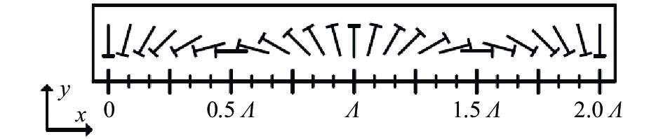
Fig. 1. Structure of LCPG
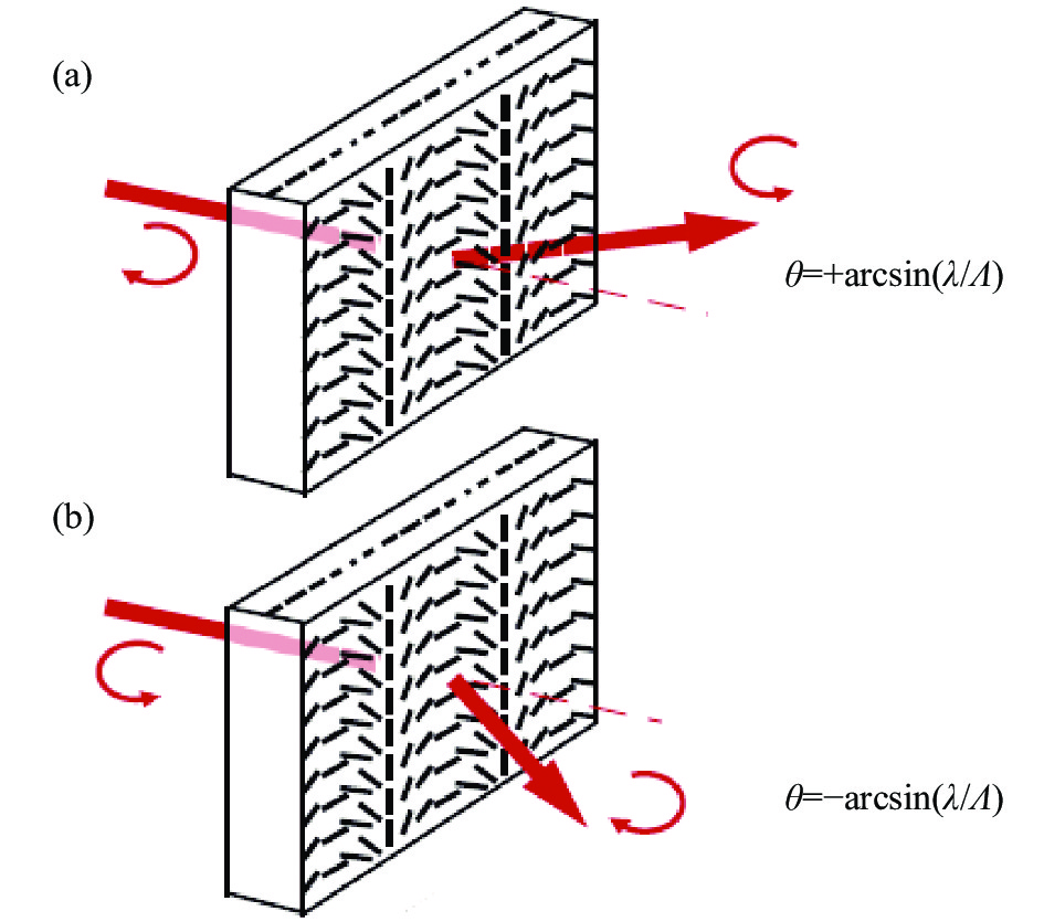
Fig. 2. Diffraction properties of passive LCPG: (a) Incident light is right-handed circular polarization; (b) Incident light is left-handed circular polarization
Fig. 3. Passive LCPG layer with two LC-AHWPs and two LCPGs
Fig. 4. Beam transceiver separation structure using OC-LCPGS
Fig. 5. Experimental diagram of OC-LCPGs receiving and transmitting separation structure verification
Fig. 6. Diffraction efficiency of different LCPG at different angles
Fig. 7. Diffraction efficiency of LCPG with mirror symmetry at different angles
| Modulation angle/(°) | Polarization state of incident light | Phase delay of AHWP1 | Polarization state after AHWP1 | Polarization state after LCPG1 | Phase delay of AHWP2 | Polarization state after AHWP2 | Polarization state after LCPG2 | | 2θ | RCPL | 0 | RCPL | LCPL | π | RCPL | LCPL | | 0 | 0 | RCPL | LCPL | 0 | LCPL | RCPL | | −2θ | π | LCPL | RCPL | π | LCPL | RCPL | | 2θ | LCPL | π | RCPL | LCPL | π | RCPL | LCPL | | 0 | 0 | LCPL | RCPL | 0 | RCPL | LCPL | | −2θ | 0 | LCPL | RCPL | π | LCPL | RCPL |
|
Table 1. Control coefficient and polarization state change at different angles
| Modulation angle/(°) | Polarization state before LCPG2 | Polarization state before AHWP2 | Phase delay of AHWP2 | Polarization state before LCPG1 | Polarization state before AHWP1 | Phase delay of AHWP1 | Polarization state before AHWP1 | | 2θ | RCPL | LCPL | π | RCPL | LCPL | 0 | LCPL | | 0 | LCPL | RCPL | 0 | RCPL | LCPL | 0 | LCPL | | −2θ | LCPL | RCPL | π | LCPL | RCPL | π | LCPL | | 2θ | RCPL | LCPL | π | RCPL | LCPL | π | RCPL | | 0 | RCPL | LCPL | 0 | LCPL | RCPL | 0 | RCPL | | −2θ | LCPL | RCPL | π | LCPL | RCPL | 0 | RCPL |
|
Table 2. Control coefficient and polarization state change at different angles reverse light path
| Realization angle | 0°(MD 1.25° layer) | −1.25°(SD 1.25° layer) | | Wave plate serial number | 0.625° | 0.625° | 0.625° | 0.625° | | Control coefficient | 0 | 0 | 1 | 1 | | Realization angle | 2.5°(MD 2.5° layer) | 2.5°(SD 2.5° layer) | | Wave plate serial number | 1.25° | 1.25° | 1.25° | 1.25° | | Control coefficient | 0 | 1 | 0 | 0 | | Realization angle | 0°(MD 5.0° layer) | −5°(SD 5.0° layer) | | Wave plate serial number | 2.5° | 2.5° | 2.5° | 2.5° | | Control coefficient | 0 | 0 | 0 | 1 | | Realization angle | 0°(MD 10.0° layer) | −10°(SD 10.0° layer) | | Wave plate serial number | 5.0° | 5.0° | 5.0° | 5.0° | | Control coefficient | 0 | 0 | 1 | 1 | | Realization angle | 20°(MD 20.0° layer) | 0°(SD 20.0° layer) | | Wave plate serial number | 10.0° | 10.0° | 10.0° | 10.0° | | Control coefficient | 0 | 1 | 0 | 0 |
|
Table 3. Control parameters of AHWP in each layer
| Layer | MD
1.25° layer
| SD
1.25° layer
| MD
2.5° layer
| SD
2.5° layer
| MD
5.0° layer
| SD
5.0° layer
| MD
10.0° layer
| SD
10.0° layer
| MD
20.0° layer
| SD
20.0° layer
| | Realization angle/(°) | 0 | −1.25 | 2.5 | 2.5 | 0 | −5 | 0 | −10 | 20 | 0 | | Polarization state after layer | RCPL | RCPL | LCPL | LCPL | LCPL | RCPL | RCPL | RCPL | LCPL | LCPL |
|
Table 4. Polarization states before and after each element of OC-LCPGS
| Layer | SD
20.0° layer
| MD
20.0° layer
| SD
10.0° layer
| MD
10.0° layer
| SD
5.0° layer
| MD
5.0° layer
| SD
2.5° layer
| MD
2.5° layer
| SD
1.25° layer
| MD
1.25° layer
| | Realization angle/(°) | 0 | −20 | 10 | 0 | 5 | 0 | −2.5 | −2.5 | 1.25 | 0 | | Polarization state after layer | LCPL | RCPL | RCPL | RCPL | RCPL | LCPL | LCPL | LCPL | RCPL | LCPL |
|
Table 5. Polarization states before and after each element of OC-LCPGS under the condition of reverse incidence
| Component | Parameter | Value | | Laser 1 | Wavelength/nm | 630 | | Optical power/mW | 3.20 | | Laser 2 | Wavelength/nm | 630 | | Optical power/mW | 1.50 | | PBS | Transmittance | P:96%;
S:94%
| | QWP | Transmittance | 96% | | HWP | Transmittance | 96% | | Grating | Linear density of grating 1/lp·mm−1 | 159 | | Linear density of grating 2/lp·mm−1 | 159 | | Linear density of grating 3/lp·mm−1 | 286 | | Linear density of grating 4/lp·mm−1 | 286 | | Transmittance | As shown in Fig.6 | | Thickness/mm | 0.45±0.04 | | Material | D263 |
|
Table 6. Composition and index of test system
| Main order angle/(°) | Transmittance of 1st measurement of S light
| Transmittance of 2nd measurement of S light
| Transmittance of 3rd measurement of S light
| Average transmittance of S light | Average transmittance of P light | | 0 | 81% | 82% | 81% | 81% | <1% | | 10 | 61% | 61% | 61% | 61% | <1% | | −10 | 61% | 61% | 61% | 61% | <1% | | 20 | 52% | 50% | 53% | 52% | <1% | | −20 | 50% | 50% | 51% | 50% | <1% | | 30 | 41% | 39% | 40% | 40% | <1% | | −30 | 36% | 37% | 36% | 36% | <1% |
|
Table 7. Transmittance at different modulation angles
| Main order
angle/(°)
| Incident angle of
LCPG1/(°)
| Incident angle of
LCPG2/(°)
| Incident angle of
LCPG3/(°)
| Incident angle of
LCPG4/(°)
| | 0 | 0 | 5 | 0 | 10 | | 10 | 0 | 5 | 10 | 0 | | −10 | 0 | −5 | −10 | 0 | | 20 | 0 | 5 | 0 | 10 | | −20 | 0 | 5 | 0 | −10 | | 30 | 0 | 5 | 10 | 20 | | −30 | 0 | −5 | −10 | 20 |
|
Table 8. Incident angle at different modulation angles